

The ASB series booster pump is an all-in-one compact and reliable automatic
multistage centrifugal booster pump, which integrates motor, pump, accumulator,
pressure switch and flow switch in one set. The flow switch equipped with the
pump prevents the pump from continuously starting and stopping under small
discharge, and provide stable water supply. It is very suitable for domestic water
supply.
Operating Conditions
1. Ambient Temperature : +5 ºC ~ +40 ºC
2. Liquid Temperature
Regular Model : +5ºC ~ +40ºC
Hot Water Model : +5ºC ~ +90ºC
3. Maximum Operating Pressure : 6 kg/cm
2
4. Rated Discharge Head / Height
ASB25(H)
: 1.5 kg/cm
2
/ 15 m
ASB50(H)
: 2.0 kg/cm
2
/ 20 m
ASB100(H) : 2.5 kg/cm
2
/ 25 m
Item
Name
Description
Item
Name
Description
Item
Name
Description
1
Motor
1
Φ
2 Poles
15
Inlet Flange Gasket
Rubber
25
Bolt
S45C
2
Bolt
S45C
16
Inlet Flange
NYLON
26
Wiring Box Cover
NYLON
3
Pump Casing
Noryl
17
Flange Bolt
SUS304
27
Bolt
S45C
18 Outet Flange Gasket
Rubber
4
Mechanical Seal
NBR
+Carbon
19
Outlet Flange
NYLON
28
Controller
Triac-Based
5
Impeller Chamber
NORYL
20
Flange Bolt
SUS304
6
Impeller
NORYL
21-1
Priming Plug
NYLON
29
Pressure Switch
For Turn-On
Pressure Setting
7
Diffuser
NORYL
21-2 Air Evacuation Plug
NYLON
30
Switch Cover
NYLON
8
Impeller
NORYL
22-0
Flow Switch Set
Flow Detection
31
Thermal Protector
Auto Reset
9
O Ring
NBR
22-1
Spring
SUS304
32
Pump Base
ABS
10
Bolt
SUS304
22-2
Stopper
NORYL
33
Bolt
S45C
11*
1
Pump Cover
NYLON
22-3
Seal O Ring
NBR
34*
2
Impeller Chamber
NORYL
12
O Ring
NBR
22-4
Locking Ring
NYLON
35*
2
Impeller
NORYL
13
Pressure Tank
SUS304
23
Seal Gasket
Rubber
36*
2
Pump Cover
NYLON
14
Pump Cover Bolt
SUS304
24
Wiring Box
NYLON
37
Motor Capacitor
Plastic Film
*1 Parts for 60 Hz models.
*2 Parts for 50 Hz models.
Installation and Piping
1. For stable operation, please mount and bolt the booster pump securely. The
installation place must be dry with good ventilation and adequate space for
future maintenance and service. A proper shelter is required for outdoor
installation; exposure to rain will damage the insulation of electrical wiring.
Construction ( ASB-H Hot water Model with stainless steel impeller.)
Item
Name
Description
Item
Name
Description
Item
Name
Description
1
Motor
1
Φ
2 Poles
13
Pressure Tank
SUS304
24
Wiring Box
NYLON
2
Bolt
S45C
14
Pump Cover Bolt
SUS304
25
Bolt
S45C
3
Pump Casing
Noryl
15
Inlet Flange Gasket
Rubber
26
Wiring Box Cover
NYLON
16
Inlet Flange
NYLON
27
Bolt
S45C
4
Mechanical Seal
Viton
+Carbon*
3
17
Flange Bolt
SUS304
28
Controller
Triac Based
5
Impeller Chamber
NORYL
18 Outlet Flange Gasket
Rubber
6
Impeller
SUS304*
3
19
Outlet Flange
NYLON
29
Pressure Switch
For Turn-On
Pressure Setting
6-1*
3
Shaft Sleeve
PPS
20
Flange Bolt
SUS304
30
Switch Cover
NYLON
7
Diffuser
NORYL
21-1
Priming Plug
NYLON
31
Thermal Protector
Auto Reset
8
Impeller
SUS304*
3
21-2 Air Evacuation Plug
NYLON
32
Pump Base
ABS
8-1*
3
Shaft Sleeve
PPS
22-0
Flow Switch Set
Flow Detection
33
Bolt
S45C
9
O Ring
NBR
22-1
Spring
SUS304
34*
2
Impeller Chamber
NORYL
10
Bolt
SUS304
22-2
Stopper
NORYL
35*
2
Impeller
SUS304*
3
10-1*
3
Shaft Sleeve
SUS304
22-3
Seal O Ring
NBR
35-1*
3
Shaft Sleeve
PPS
11*
1
Pump Cover
NYLON
22-4
Locking Ring
NYLON
36*
2
Pump Cover
NYLON
12
Tank O Ring
Silicon Rubber*
3
23
Seal Gasket
Rubber
37
Motor Capacitor
Plastic Film
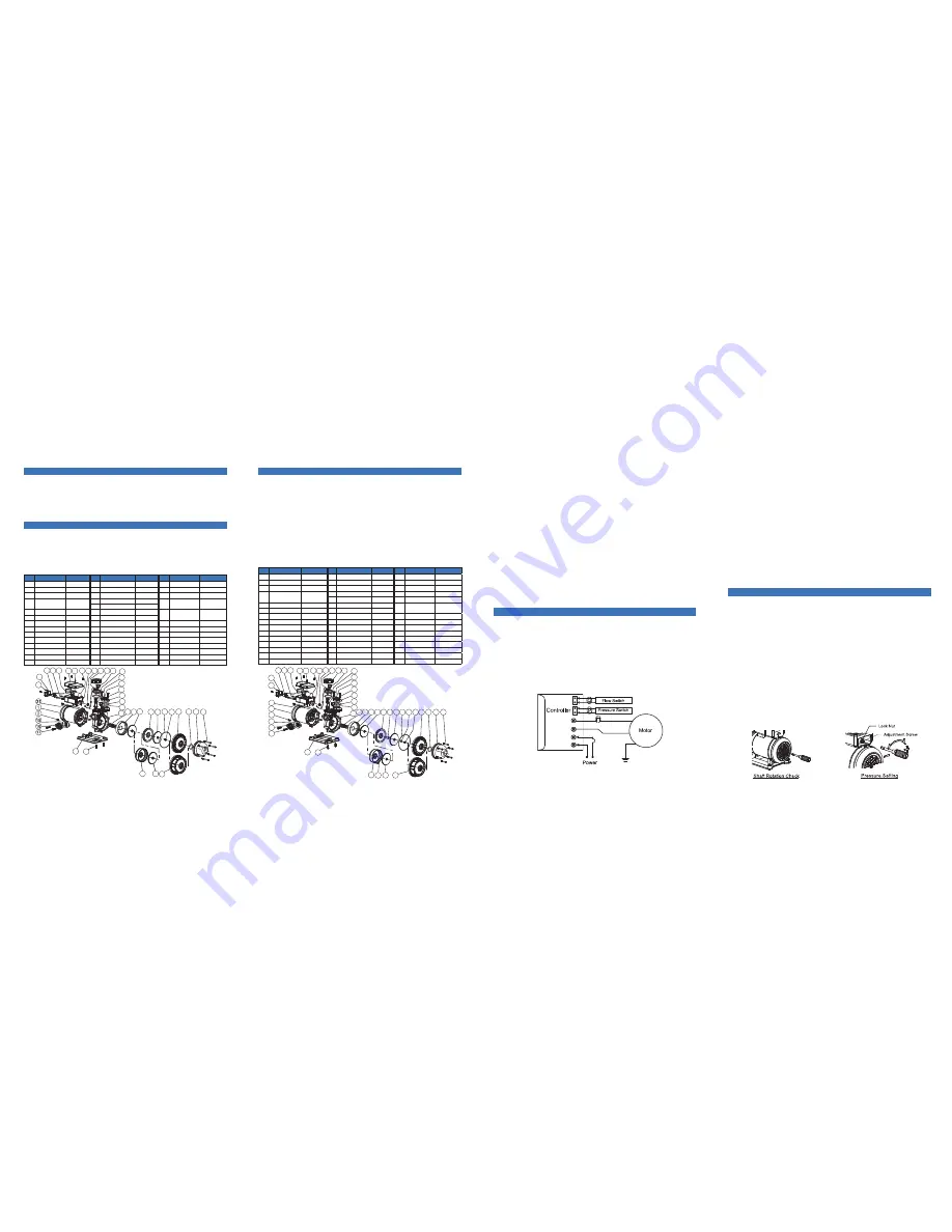
Operation and Important Notes
Pressure Switch Adjustment
(a) Single Voltage Model Wiring
Description
Construction ( ASB Regular model with thermoplastic impeller.)
14
13
12
11
10
9
8
7
6
5
4
3
18
19
20
23
24
37
27
26
28
25
29
30
27
30
27
31
15
16
17
32
33
32
33
34
35 36
34
35
36
14
13
12
11
10
9
8
7
21-2
35-1
22-2
22-1
21-1
22-4
22-0
23
24
37
27
26
28
25
29
21-1
6-1
8-1
22-4
22-0
22-3
18
19
20
21-2
22-2
22-1
10-1
22-3
1
2
6
5
4
3
2. The pump should be installed as close as to the reservoir or well. For hot
water (40~90ºC) pumping, negative inlet pressure application is required to
avoid cavitations. Piping joints should be fitted carefully to prevent leak. Leak
in the suction piping will cause the pump suction capacity lost, while leak in
the discharge piping will cause a high frequency ON/OFF motor operation
while the faucets valves are closed.
*3 Parts or materials for hot water models
only.
*2 Parts for 50 Hz models.
*1 Parts for 60 Hz models.
3. Protection rubber films within the center of suction/discharge flange gaskets
(Part No. 15 & 18) muse be removed during installation.
4. Be careful not to allow the foreign objects (PVC adhesive gum, dirt, sand etc)
into the pump, otherwise the pump will be damaged and shortened the life.
It is recommended to use a strainer to prevent that.
5. Check the voltage and wiring of the motor power according to the connecting
diagram shown below or inside the cover. Be sure to arrange earth or circuit
breaker against electric leakage in accordance with local government electrical
code.
6. The pump thermal protector (Part No. 31) is designed to protect the pump
from dry run. It is also used to prevent hot water pumping which will damage
the pump structure. The electrical power will be cut off after several minutes
while dry run occurs, and will be turned on periodically. Shut off the electrical
power manually is recommended during the water shortage period to save
the energy.
7. An auto-reset thermal protector is equipped with the motor winding. Power
will be cut off when the motor winding temperature is abnormal, and will
restart when the abnormal temperature back to normal.
1. Before set the power on, the pump chamber and suction pipe must be filled
with water in accordance with the following:
2. Insert a crossed screwdriver into motor shaft end, and turn the shaft several
turns clockwise to check whether the pump can be rotated freely. If not,
disassemble and clean the pump chamber.
3. Double check the voltage and wiring of the motor power and then turn the
power switch ON. Open faucet or water appliances on the discharge piping
side. The water should be delivered after several seconds.
4. If the water does not be delivered after several minutes, turn off the pump
immediately. Repeat step 1 to pour water into the pump and suction piping,
and switch power ON and OFF continuously.
5. Once the water is pumped out, close and open the water appliances on the
discharge side repeatedly to check automatic ON/OFF operation.
6. Measure the motor current and check with the data shown on the nameplate.
If the current is over, check the voltage again.
7. When re-start the pump after long term shut down, please repeat step1~6 to
ensure the normal operation.
The pressure switch set is designed inside the control box. In general, the
pressure has been set by factory properly to meet most situations. However,
for some special cases, when the pump cannot operate normally, it can be
adjusted easily. Please check the trouble shooting procedures, and read the
following instructions carefully before to do it. For pressure adjustment, first
remove the switch cover, and loose the lock nut counterclockwise by using a
12mm wrench.
1. Motor fails to stop
It is because of the pressure setting too high. By using a flat-end screwdriver,
turn the screw counterclockwise slowly, until the motor stop; then, turn an extra
small rotation, about 5 degrees. Finally, check if the motor can start normally.
2. Motor fail to start
It is because of the pressure setting too low. By using a flat-end screwdriver,
turn the screw clockwise slowly, until the motor start, then an extra small rotation,
about 5 degree, is added. Finally, check if the motor can stop normally.
3. After the pressure setting, screw the lock nut, and put the cover back.
◎
For the negative inlet pressure application ( inlet water level is below the pump
input ), remove the priming plugs (Part No. 21-1 or 21-2), and pour water into
the pump via priming hole completely. Then, secure the priming plugs back.
◎
For the positive inlet pressure application ( inlet water level is higher than
pump input ), loose the priming plug (Part No. 21-2), and then secure it after
the water drain out from the priming hole.


