21
VFH InverterFlex
®
- Ductless Mini-Split
AITONS EQUIPMENT
INDOOR/OUTDOOR
COMMUNICATING
CABLE
Indoor Wiring
1. Wiring must conform to all local and national
electric codes
2. Lift the indoor unit’s panel up, remove the
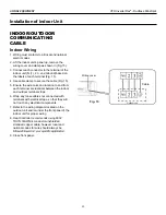
wiring cover and clamp as shown in (Fig.15).
3. Connect each conductor to the terminal of the
indoor unit (N (1), 2 3, and Ground) based on
the labels of each terminal (Fig. 15).
4. Use cable clamp to secure the cable (Fig. 15).
5. Ensure the wire color and location to and from
each terminal are identical between the indoor
and outdoor terminal strips.
6. Wrap any loose cables not connected with
terminals with electrical tape, so that they will
not touch any electrical components.
7. Refer to the wiring diagram located on the
outdoor unit and/or under the front panel of the
indoor unit for proper wiring
8. Heat Controller recommends using 600V
THHN 14AWG/4 conductor unshielded
stranded copper cable, however local and
national codes for wire should always be
9. Close front panel.
Installation of Indoor Unit
Fig. 15
Wiring cover
Cable
Outdoor unit


