background image


1. 


Safety rules


This manual provides information on the safe use of the UPS. Before unpacking and installing the UPS, 
read its contents and follow its instructions. 


FULFILLED STANDARDS - EXECUTION 

EN 62040-3 

Uninterruptible Power Systems (UPS):  Methods for determining 
the characteristics and test requirements. 


FULFILLED STANDARDS - ELECTROMAGNETIC COMPATIBILITY 

EN 62040-2 :2006 C3 

Unsupported 

Power 

Systems 

(UPS): 

Electromagnetic 

Compatibility. 

EN 61000-2-2 :2002 

Electromagnetic Compatibility (EMC): Environment. Compatibility 
levels  for  conducted  low-frequency  disorders  and  signaling  in 
public low-voltage power supply systems. 

EN 61000-4-2 :2009   
 

Electromagnetic Compatibility (EMC): Testing and measurement 
methods - electrostatic discharge immunity test. 

EN 61000-4-3 :2006 
+A1 :2008 +A2 :2010 

Electromagnetic  Compatibility  (EMC):  Test  and  Measurement 
Methods - Radio Frequency Electromagnetic Field Immunity Test. 
 

EN 61000-4-4 :2004 
+A1 :2010 

Electromagnetic  Compatibility  (EMC):  Test  and  Measurement 
Methods - Test of immunity to a series of fast electrical transients. 
 

EN 61000-4-5 :2006 

Electromagnetic Compatibility (EMC): Testing and Measurement 
Methods - Surge Immunity Test. 

EN 61000-4-6 :2009 

Electromagnetic  compatibility  (EMC):  Test  and  measurement 
methods - Immunity to conducted disturbances, induced by radio 
frequency fields. 

EN 61000-4-8 :2010 

Electromagnetic Compatibility (EMC): Testing and measurement 
methods - Testing resistance to magnetic field at the frequency of 
the power grid. 


The device complies with the Directive 2004/108 / EC (EMC). 


FULFILLED STANDARDS - SAFETY 

EN 62040-1 :2008 

Uninterruptible Power Systems (UPS): General requirements and 
requirements for UPS safety. 

EN 60950-1:2006 

Information technology devices. Security. 

IEC 60417 

Symbols used on devices. 

 
The device complies with the 2006/95 / EC (LVD) directive. 


警告


危 险


警告


危 险


警告


危 险


Содержание COVER CORE 10K

Страница 1: ...E 6 10 kVA User manual The content of this document is the copyright of the publisher and may not be reproduced without prior permission The right to modify the design and specifications is reserved w...

Страница 2: ...2 LED indicators 10 4 3 LCD display 11 4 4 Alarm signals 12 4 5 LCD display letter abbreviations 12 4 6 UPS settings menu 13 4 7 Description of the UPS operation modes 15 4 8 UPS warnings and audible...

Страница 3: ...Compatibility EMC Test and Measurement Methods Radio Frequency Electromagnetic Field Immunity Test EN 61000 4 4 2004 A1 2010 Electromagnetic Compatibility EMC Test and Measurement Methods Test of immu...

Страница 4: ...ircuit should be protected with an appropriate overcurrent circuit breaker The UPS has its own battery power source so there may be voltage on the output strip even though the UPS is not connected to...

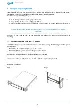
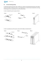
Страница 5: ...chanical damage shock and impact only transport the UPS in its original packaging All models of the CORE 6K and 10K power supplies are suitable for both horizontal and vertical mounting 2 1 Horizontal...

Страница 6: ...ower supply and enable its stable placement in a vertical position The set of stands includes short and long connecting elements depending on the width of the UPS set In order to place the power suppl...

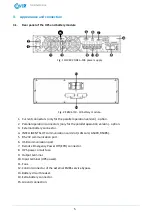
Страница 7: ...y for the parallel operation version option 3 External battery connector 4 INTELLIGENT SLOT communication card slot LAN card AS400 RS485 5 RS 232 communication port 6 USB communication port 7 Remote E...

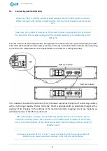
Страница 8: ...attery modules as in the figure below If it is necessary to extend the autonomy time the power supply has the option of connecting a battery with a much larger capacity thanks to the fact that it is e...

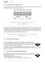
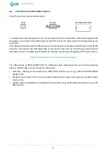
Страница 9: ...Cables should be connected and arranged in such a way that no one can accidentally disconnect them 3 4 Connection of remote EPO switch The UPS is equipped with an EPO port for connecting a remote eme...

Страница 10: ...n the events that occur on the UPS e g power failure low battery level The software also allows for ongoing monitoring and logging of UPS event history RS232 and USB ports cannot be used simultaneousl...

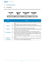
Страница 11: ...n to the previous menu page TEST UP Battery test Press and hold for more than 0 5 seconds during normal operation of the UPS to activate the test Up arrow Key to scroll up to the previous line in the...

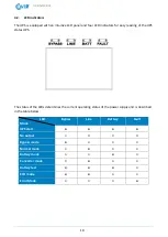
Страница 12: ...r easy reading of the UPS status UPS The status of the LEDs determines the current operating status of the power supply and is described in the table below LED Mode Bypass Line Battery Fault UPS start...

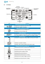
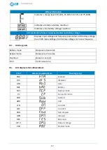
Страница 13: ...tput voltage Hz output frequency Vdc battery voltage Load information Indicates the load level of 0 24 25 49 50 74 and 75 100 Indicates an overload condition Indicates a short circuit condition at the...

Страница 14: ...voltage Vac 230V mains voltage Vdc battery voltage Hz mains frequency 4 4 Alarm signals Battery mode Beep every 4 seconds Bypass mode Beep every 2 minutes Overload Beep 2x second Error Continuous tone...

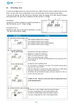
Страница 15: ...240Vac output voltage 02 The output frequency 60 Hz CVCF mode 50 Hz Normal mode ATO Parameter 2 The output frequency Allows you to select the frequency 50Hz The output frequency is 50Hz 60Hz The outp...

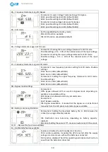
Страница 16: ...ault 58Hz Parameter 3 Setting the upper frequency tolerance for ECO mode Possible settings 50Hz 52Hz 54Hz default 52Hz 60Hz 62Hz 64Hz default 62Hz 08 Bypass mode settings Parameter 2 OPN Bypass allowe...

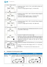
Страница 17: ...le to make changes Parameter 2 Indicates the OP V output voltage Parameter 3 Indicates the UPS output voltage measured inside the UPS Using the arrow keys calibrate the value of the output voltage to...

Страница 18: ...the event of a power failure or when the supply voltage is beyond the tolerance allowing the output voltage to be kept within the required tolerance the UPS switches to battery operation The beep sou...

Страница 19: ...within 30 min Beeps every second 4 9 Warning codes Code Warning Code Ostrze enie 01 Batteries not connected 21 EC supply differences parallel operation 07 Battery overcharging 22 Differences on Bypas...

Страница 20: ...age is too low 14 Short circuit on the inverter output 1A Reverse power at the inverter output 21 Battery thyristor short circuit 24 Inverter relay shorted 2A Charger short circuit 31 CAN communicatio...

Страница 21: ...rmal operation Attention In order to obtain the maximum autonomy the batteries should be charged at least 10 hours after the first use The maximum capacity of the battery is obtained after two full di...

Страница 22: ...o go to the next step 3 Switch the external Maintenance Bypass from BYPASS position to UPS position 4 To turn on the power supply start the inverter press the ON button on the UPS display and hold it...

Страница 23: ...d damaging them Depending on the storage temperature the power supply should be connected at least every 6 months to charge the battery Typically the batteries are charged in 4 hours to 90 capacity bu...

Отзывы: