background image

11


Rack Mounting 

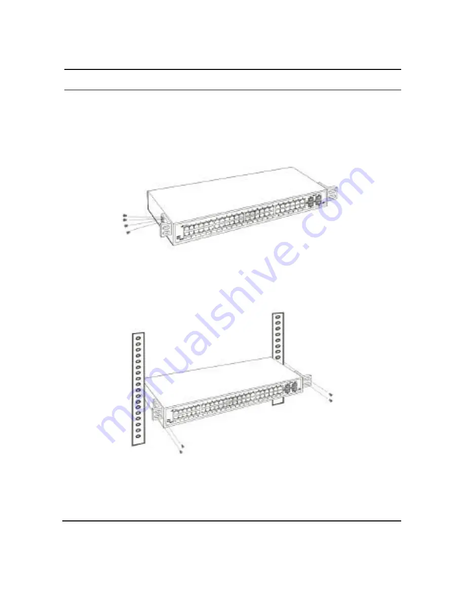
The switch can be mounted in an EIA standard-size, 19-inch rack, 
which can be placed in a wiring closet with other equipment.  Attach 
the mounting brackets at the switch’s front panel (one  on each side), 
and secure them with the provided screws. 


Figure 2. Combine the Switch with the provided screws  

Then, use screws provided with the equipment rack to mount each 
switch in the rack. 


Figure 3. Mount the Switch in the rack 

Содержание 48-Port 10

Страница 1: ...48 Port 10 100 1000Mbps Gigabit Ethernet Web Smart Switch with 48 10 100 1000Mbps UTP ports plus 4 1000Mbps mini GBIC ports share User s Guide ...

Страница 2: ...equency energy and if not installed and used in accordance with this user s guide may cause harmful interference to radio communications Operation of this equipment in a residential area is likely to cause harmful interference in which case the user will be required to correct the interference at his or her own expense CE Mark Warning This is a Class A product In a domestic environment this produc...

Страница 3: ...s not compromised c Mechanical Loading mounting of the equipment in the rack should be such that a hazardous condition is not achieved due to uneven mechanical loading d Circuit Overloading Consideration should be given to the connection of the equipment to the supply circuit and the effect that overloading of circuits might have on over current protection and supply wiring Appropriate considerati...

Страница 4: ......

Страница 5: ...5 VLAN Virtual Local Area Network 6 Features 6 Unpacking and Installation 9 Unpacking 9 Installation 10 Rack Mounting 11 Connecting Network Cable 12 AC Power 12 Identifying External Components 13 Front Panel 13 Rear Panel 14 Understanding LED Indicators 15 Power and System LEDs 15 Ports 1 48 Status LEDs 16 mini GBIC 45F 48F Status LEDs 16 Configuration 17 ...

Страница 6: ...uring the Switch 23 Login 24 Setup Menu 25 Configuring Setup Setting 26 Port Settings 26 VLAN Settings IEEE 802 1Q VLAN 28 Trunk Setting 31 Mirror Setting 32 Device Status 33 Statistic 34 System Setting 35 Trap Setting 36 Password Setting 37 Backup Setting 37 Reset Setting 38 Logout 38 Technical Specifications 39 ...

Страница 7: ...et and 10Mbps Ethernet network capabilities in a highly flexible package Purpose This guide discusses how to install your 48 Port 10 100 1000Mbps Gigabit Ethernet Web Smart Switch Terms Usage In this guide the term Switch first letter upper case refers to your 48 Port 10 100 1000Mbps Gigabit Ethernet Web Smart Switch and switch first letter lower case refers to other Ethernet switches ...

Страница 8: ......

Страница 9: ...d upgrade without wasting a company s existing investment in hardware software and trained personnel The increased speed and extra bandwidth offered by Gigabit Ethernet is essential to coping with the network bottlenecks that frequently develop as computers and their busses get faster and more users use applications that generate more traffic Upgrading key components such as your backbone and serv...

Страница 10: ...ling the need for high performance networks A number of high speed LAN technologies have been proposed to provide greater bandwidth and improve client server response times Among them 100BASE T Fast Ethernet provides a non disruptive smooth evolution from the current 10BASE T technology The non disruptive and smooth evolution nature and the dominating potential market base virtually guarantees cos...

Страница 11: ...for network transmission capacity The switch acts as a high speed selective bridge between the individual segments The switch without interfering with any other segments automatically forwards traffic that needs to go from one segment to another By doing this the total network capacity is multiplied while still maintaining the same network cabling and adapter cards Switching LAN technology is a ma...

Страница 12: ...be used to create multiple broadcast domains thus eliminating the need of expensive routers Features u 48 10 100 1000Mbps 1000BASE T Auto negotiation Gigabit Ethernet ports u 4 x 1000Mbps mini GBIC Auto Sense for optional mini GBIC transceiver to extend distance share with 4 1000BASE T ports u All RJ45 ports support auto MDI MDIX so there is no need to use cross over cables or an up link port u Ha...

Страница 13: ... mode ports u Supports IEEE 802 1Q VLAN u Supports Port base QoS u Supports ten Trunk groups u Supports Port mirroring u Supports Port setting for Speed Disable Flow control u Easy configuration via WEB Browser u Easy setting via Web Management Utility u Standard 19 Rack mount size ...

Страница 14: ......

Страница 15: ...should contain the following items u One 48 Port 10 100 1000Mbps Gigabit Ethernet Web Smart Switch u One AC power cord suitable for your area s electrical power connections u Four rubber feet to be used for shock cushioning u Screws and two mounting brackets u CD Rom with Web Management Utility and User s Guide If any item is found missing or damaged please contact your local reseller for replacem...

Страница 16: ...tors such as motors vibration dust and direct exposure to sunlight Leave at least 10cm of space at the front and rear of the hub for ventilation Install the Switch on a sturdy level surface that can support its weight or in an EIA standard size equipment rack For information on rack installation see the next section Rack Mounting When installing the Switch on a level surface attach the rubber feet...

Страница 17: ...loset with other equipment Attach the mounting brackets at the switch s front panel one on each side and secure them with the provided screws Figure 2 Combine the Switch with the provided screws Then use screws provided with the equipment rack to mount each switch in the rack Figure 3 Mount the Switch in the rack ...

Страница 18: ...o transform to MDI II or MDI X type so you can just make an easy connection that without worrying if you are using a standard or crossover RJ45 cable There are additional 4 ports mini GBIC slot for optional mini GBIC module AC Power The Switch used the AC power supply 100 240V AC 50 60 Hz The power switch is located at the rear of the unit adjacent to the AC power connector and the system fan The ...

Страница 19: ...I MDIX crossover detection function this function gives true plug and play capability just need to plug in the network cable to the hub directly and don t care if the end node is NIC Network Interface Card or switch and hub These ports can operate in half duplex mode for 10 100Mbps and full duplex mode for 10 100 1000Mbps Note When the port was set to Forced Mode the Auto MDI MDIX will be disabled...

Страница 20: ... Rear Panel The rear panel of the Switch consists of an AC power connector The following shows the rear panel of the Switch Figure 5 Rear panel of the Switch AC Power Connector This is a three pronged connector that supports the power cord Plug in the female connector of the provided power cord into this connector and the male into a power outlet Supported input voltages range from 100 240V AC at ...

Страница 21: ... Figure 6 LED indicators of the Switch Power and System LEDs POWER Power Indicator On When the Power LED lights on the Switch is receiving power Off When the Power turns off or the power cord has improper connection System Management Indicator Blinking When the CPU is working the System LED is blinking On Off The CPU is not working ...

Страница 22: ... Gigabit Ethernet network the Speed LED will lights green Amber When the related port was connected to 100Mbps Fast Ethernet network the Speed LED will lights amber Off When the related port was connected to 10Mbps Ethernet network the Speed LED will lights off mini GBIC 45F 48F Status LEDs Link ACT On When the LC fiber line connected to the mini GBIC module is installed and connected to a network...

Страница 23: ...t Utility The following gives instructions guiding you through the installations of the Web Management utility 1 Insert the Utility CD in the CD Rom Drive 2 From the Start menu on the Windows desktop choose Run 3 In the Run dialog box type D Web Management Utility setup exe D depends where your CD Rom drive is located and click OK 4 Follow the on screen instructions to install the utility 5 Upon c...

Страница 24: ...ils instruction follow the below section Discovery List This is the list where you can discover all the Web management devices in the entire network By pressing the Discovery button you can list all the Web Management devices in the discovery list Double click or press the Add to monitor list button to select a device from the Discovery List to the Monitor List ...

Страница 25: ... All the Web Smart Device in the Monitor List can be monitored you can also receive the trap and show the status of the device System word definitions in the Monitor List l S Shows the system symbol of the Web Smart device represent for device system is not alive l IP Address Shows the current IP address of the device l MAC Address Shows the device MAC Address l Protocol version Shows the version ...

Страница 26: ...ed a Trap Information window will pop out it will show the trap information including the Symbol Time Device IP and the Event occurred Figure 9 The symbol represents the trap signal arise this symbol will disappear after you review and click on the event record Figure 9 Note In order to receive Trap information switch has to be configured with Trap IP and Trap Events in Web browser which are avail...

Страница 27: ...ation Setting window will pop out as Figure 10 after filling up the data that you want to change you must fill up the password and press the Set to process the data changed immediately The default password of this 48 Port 10 100 1000Mbps Gigabit Ethernet Web Smart Switch configuration is admin Figure 10 Configuration Setting Password Change You can use this Password Change when you need to change ...

Страница 28: ...n the Web Management Utility have four main tabs File View Options and Help In the File TAB there are Monitor Save Monitor Save As Monitor Load and Exit l Monitor Save To record the setting of the Monitor List to the default when you open the Web Management Utility next time it will auto load the default recorded setting l Monitor Save As To record the setting of the Monitor List in appointed file...

Страница 29: ...there is About function it will show out the version of the Web Management Utility Configuring the Switch The 48 Port 10 100 1000Mbps Gigabit Ethernet Web Smart Switch has a Web GUI interface for smart switch configuration The Switch can be configured through the Web Browser A network administrator can manage control and monitor the switch from the local LAN This section indicates how to configure...

Страница 30: ...ber between 2 and 254 and the default subnet mask is 255 255 255 0 Open Internet Explorer 5 0 or above Web browser Enter IP address http 192 168 0 1 the factory default IP address setting to the address location Figure 13 Or through the Web Management Utility you do not need to remember the IP Address select the device shown in the Monitor List of the Web Management Utility to settle the device on...

Страница 31: ...n page appears find the Setup menu in the left side of the screen Figure 16 Click on the setup item that you want to configure There are eleven options Port Settings VLAN Settings Trunk Setting Mirror Setting Device Status Statistic System Settings Trap Setting Password Setting Backup Setting and Reset Setting as shown in the Main Menu screen ...

Страница 32: ...ings In Port Settings menu Figure 17 this page will show each port s status press the ID parameter to set each port s Speed Flow Control QoS priority and Link Status When you need to renew the posted information press the Refresh button The Link Status in the screen will show the connection speed and duplex mode else this dialog box will show down when the port is disconnected ...

Страница 33: ...t when transferring the media type Fiber to Copper or Copper to Fiber Note 2 The priority of Gigabit Fiber port is higher than Copper To change the port setting click on the ID parameter to enter to the selected port to configure its Speed Disable Flow control and QoS setting Figure 18 ...

Страница 34: ...gh to determine the port will always transfer their data first VLAN Settings IEEE 802 1Q VLAN A VLAN is a collection of switch ports that make up a single broadcast domain You can configure a VLAN for a single switch or for multiple switches When you create a VLAN you can control traffic flow and ease the administration of moves adds and changes on the network by eliminating the need to change phy...

Страница 35: ... VID group setting select the VID group and change the setting and press the Apply button to save the settings Figure 19 VLAN Settings Port VID Setting When you select Port VLAN setting fill in each port s PVID value between 1 and 4094 Figure 20 ...

Страница 36: ...was checked when the packet was tagged then the packet will forward directly to the destination port and when the packet was untagged this function will add the PVID value in the header of the packet and forward to the destination port Otherwise when the port dialog box was unchecked all of the packet will just forward to destination directly Figure 21 ...

Страница 37: ...ing groups to be set and there are default ports in each member Checked Enable to use the trunk function select the ports in each member to be trunk and click Apply to activate the selected trunk group Figure 22 Trunk Settings Be sure that the selected trunk setting port must connect to the device with a same VLAN group ...

Страница 38: ...assigning a source port from which to copy all packets and a sniffer port where those packets will be sent The selection of the sniffer mode is as follow TX transmit mode this mode will duplicate the data transmit from the source port and forward to the sniffer port RX receive mode this mode will duplicate the data that send to the source and forward to the sniffer port Both transmit and receive m...

Страница 39: ...Click on the Status to present the device status on this screen it will show the System Status Port Status VLAN Status Trunk Status and Mirror Status Press Refresh when you need to renew the posted information Figure 24 ...

Страница 40: ...34 Statistic The Statistic Menu screen will show the status of each port packet count Figure 25 For Detail packet information click on the ID parameter as Figure 26 Figure 26 ...

Страница 41: ...you can easily recognize the device by using the System Name and the Location Name The Login Timeout is to set the idle time out for security issue when there is no action in running the Web Smart Utility and the time is up you must re login to Web Smart Utility before you set the Utility Fill up the IP Address Subnet Mask and Gateway for the device Figure 27 ...

Страница 42: ...ice Bootup a trap when booting up the system Illegal Login a trap when there is using a wrong password login and it will record from where the IP to be login Fiber Port Events Monitoring the Fiber port status Link Up Link Down a trap when there is linking status happens in fiber port Abnormal Receive Error a trap when there are receive data error in fiber port Abnormal Transmit Error a trap when t...

Страница 43: ...witch use this function to change the password If you forget the password press the Reset button in the rear panel of the Switch the current setting includes VLAN Port Setting etc will be lost and the Switch will restore to the default setting Figure 29 Set Password Backup Setting The backup tools help you to backup the current setting of the Switch Once you need to backup the setting press the Ba...

Страница 44: ...t button helps you to reset the device back to the default setting from the factory Be aware that the entire configuration will be reset the IP address of the device will be set to default setting 192 168 0 1 Figure 31 Reset Setting Logout When press this function the web configuration will go back to first Login page Figure 32 Logout ...

Страница 45: ...ps full duplex Topology Star Network Cables 10BASET 2 pair UTP Cat 3 4 5 up to 100m 100BASE TX 2 pair UTP Cat 5 up to 100m 1000BASE T 4 pair UTP Cat 5 up to 100m Fiber module mini GBIC Fiber module Number of Ports 48 10 100 1000Mbps Auto MDIX RJ 45 ports 4 mini GBIC fiber slot Physical and Environmental AC inputs 100 240V AC 50 60 Hz internal universal power supply Power Consumption 70 Watts Max T...

Страница 46: ... Table 8K entries per device Packet Filtering Forwarding Rate 10Mbps Ethernet 14 880 pps 100Mbps Fast Ethernet 148 800 pps 1000Mbps Gigabit Ethernet 1 488 000 pps MAC Address Learning Automatic update Transmits Method Store and forward RAM Buffer 1632KBytes per device ...

Отзывы: