background image

2.Hardware Installation

This section will guide you through the installation of the motherboard. The topics covered in this section are:
       Preparing the motherboard


.


Installing the CPU


.


Installing the CPU fan


Installing the memory


Installing the motherboard


Connecting cables and setting switches

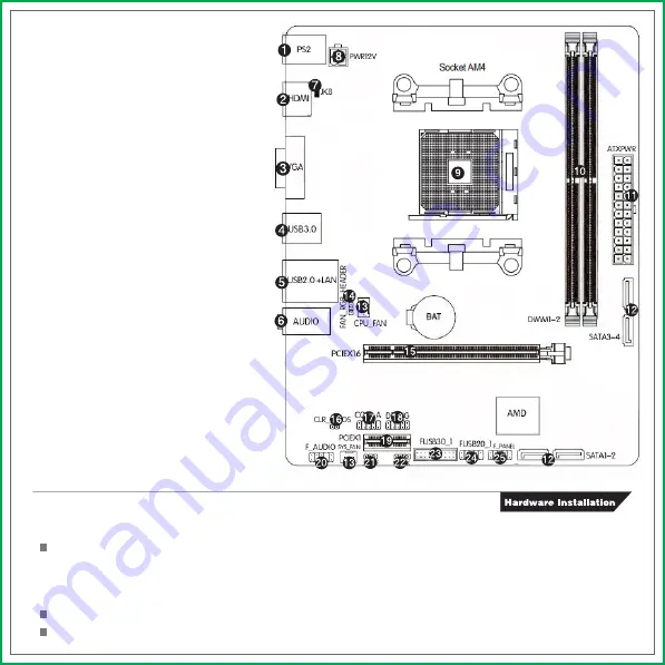
1.PS/2 Mouse and Keyboard port
2.Connect to HDMI monitor
3.Connect to VGA monitor
4.Connect to USB3.0 devices
5.Connect to USB2.0 devices and LAN
6.Audio devices
7.PS2 Mouse/ Keyboard boot jumper
8.4-pin ATX 12V Power connector
9.AMD AM4 socket
10.DIMM slots
11.24-pin ATX Power connector
12.SATA 3.0 ports
13.Fan connector(CPU_FAN,SYS_FAN)
14.FAN_RGB_header
15.PCI-Express 3.0 X16 slot,for VGA Card
16.clear CMOS jumper
17.COM header
18.Debug card connector
19.PCI Express x1 slot
20.Front panel audio connector
21.SPDIF header
22.Speaker connector
23.USB 3.0 header
24.USB 1.1/2.0 header
25.System panel connector

1.3.Motherboard Layout

Содержание A320M-K PRO V14

Страница 1: ...p www colorful cn 1 2 MOTHERBOARD SPEC CPU Supports Socket AM4 Support AMD AM4 CPUS Chipset AMD A320 A320M K PRO V14 AMD B350 AB350M K PRO V14 Main Memory Slots Dual Channel DDR4 2666 OC 2400 2133MHZ support Offer 2 DIMM slots 1 24 pin ATX Power connector 1 4 pin ATX 12V Power connector 1 Front panel audio connector F_AUDIO 1 System panel connector F_PANEL 1 USB2 0 headers F USB20_1 1 USB3 0 heade...

Страница 2: ...A monitor 4 Connect to USB3 0 devices 5 Connect to USB2 0 devices and LAN 6 Audio devices 7 PS2 Mouse Keyboard boot jumper 8 4 pin ATX 12V Power connector 9 AMD AM4 socket 10 DIMM slots 11 24 pin ATX Power connector 12 SATA 3 0 ports 13 Fan connector CPU_FAN SYS_FAN 14 FAN_RGB_header 15 PCI Express 3 0 X16 slot for VGA Card 16 clear CMOS jumper 17 COM header 18 Debug card connector 19 PCI Express ...

Страница 3: ... a 90 degree angle 2 Look for the gold arrow of the APU The gold arrow should point as shown in the picture The APU can only fit in the correct orientation 3 If the APU is correctly installed the pins should be completely embedded into the socket and can not be seen Please note that any violation of the correct installation procedures may cause permanent damages to your motherboard 4 Press the APU...

Страница 4: ... the chassis supplier Be sure that the CPU fan assembly has enough clearance for the chassis covers to lock into place and for the expan sion cards Also make sure the CPU Fan assembly is aligned with the vents on the covers 2 3 Installing Memory DIMMs Your new motherboard has 2 slots for DDR4 memory They support dual channel DDR4 memory technology There must be at least one memory bank populated t...

Страница 5: ...ting hole on the motherboard it is recom mended that you remove that stud to prevent the possibility of a short circuit 1 Carefully place the motherboard onto the studs spacers located inside the chassis 2 Align the mounting holes with the studs spacers 3 Align the connectors to the I O shield 4 Ensure that the fan assembly is aligned with the chassis vents according to the fan assembly instructio...

Страница 6: ...o I O module that supports either High Definition Audio or AC 97 audio standard Connect one end of the front panel audio I O module cable to this connector 2 7 5 USB2 0 connectors These connectors are for USB 2 0 ports Connect the USB module cable to any of these connectors then install the module to a slot opening at the back of the system chassis These USB connectors comply with the USB 2 0 spec...

Страница 7: ...hes when data is read from or written to the HDD System warning speaker 4 pin SPEAKER This 4 pin connector is for the chassis mounted system warning speaker The speaker allows you to hear system beeps and warnings ATX power button soft off button 2 pin PWRSW This 2 pin connector is for the system power button Reset button 2 pin RESET This 2 pin connector is for the chassis mounted reset button for...

Страница 8: ...nd 2 together using the jumper cap 2 Return the jumper setting to normal pin 2 or Remove the jumper cap 3 Turn the AC power supply back on Clear CMOS PROCEDURE The PCI Express x16 slot is reserved for a graphics or video card The bandwidth of the x16 slot is up to 8GB sec When installing a PCI Express x16 card be sure the retention clip snaps and locks the card into place If the card is not seated...

Страница 9: ...ces 2 7 11 COM header COM_A This SPDIF header is for SPDIF audio devices 2 7 13 SPDIF header JSPDIF This SPEAK header is for Speaker serial devices 2 7 14 SPEAK header SPEAK This 4 pin header is for FAN with LED light 2 7 12 FAN_RGB_HEADER ...

Страница 10: ...You can connect a network cable to it LAN Jack Lie In Blue Line Out Green Side surround speakers connector Side R L Gray Onboard VGA connect to Monitor VGA Onboard HDMI port connect to HDMI Monitor HDMI These connectors are for attaching USB devices such as keyboard mouse or other USB compatible devices USB Ports These jumpers set PS 2 Mouse Keyboard to start up functions you also need to open thi...

Страница 11: ...The products name we mentioned in this manual is only for identifying all of the brands belong to other company The registered trademarks of IBM VGA and PS 2 belong to International Business Machines The registered trademarks of Intel Pentium Pentium Ⅱ Celeron Pentium III and Pentium 4 belong to Intel The registered trademark of Athlon belongs to Advanced Micro Devices Inc The registered trademark...

Страница 12: ...5 Technical Support ...

Отзывы: