Data Enabler Pro Product Guide
11
2. If necessary, cut both ends of the cable jacket to
expose the wire pairs. Do not strip the wire pairs.
The Brown, Brown/White, Blue, and Blue/White wires
are not used and should be capped and turned back.
3. Run one end of the cable through a cable connector
installed on the output side of the first Data Enabler
Pro device in the series (the side with two openings).
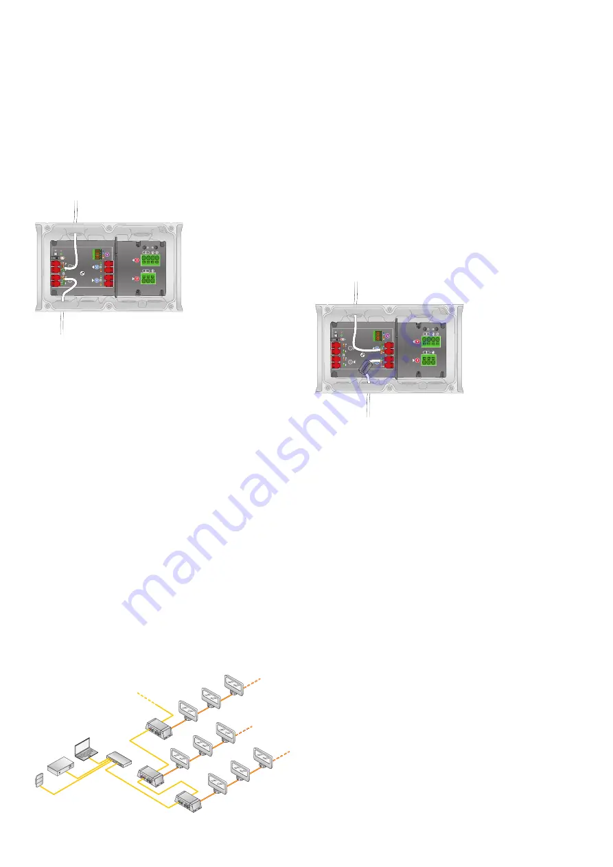
4. Locate the DMX output pivot connectors inside
the Data Enabler Pro housing. Open both pivot
connectors.
5. From right to left, following the wire color codes
printed on the data board, insert the Orange/White,
Orange, Green/White, and Green wires into the pivot
connector’s wire entry holes.
6. While holding the wires firmly in place, push down on
the pivot connectors until they click shut.
7. Run the free end of the cable to the next Data
Enabler Pro device in the series, and make DMX
data input connections as described in the previous
section.
8. Repeat for each Data Enabler Pro device in the series.
9. Terminate the last Data Enabler Pro device in the
series using the termination switch.
Series Connection Using Ethernet
You can connect up to 25 Data Enabler Pro devices in
series. Use additional Ethernet switch ports to connect
additional Data Enabler Pro devices to your network.
In Ethernet networks, maximum run lengths for data
cables are 100 m (328 ft) between Ethernet devices
without a repeater.
1. Cut a sufficient length of CAT 5e or better cable to
connect the first Data Enabler Pro device in a series
with the next.
2. If necessary, cut both ends of the cable jacket to
expose the wire pairs. Do not strip the wire pairs.
The Brown, Brown/White, Blue, and Blue/White wires
are not used and should be capped and turned back.
3. Run one end of the cable through a cable connector
installed on the output side of the first Data Enabler
Pro device in the series (the side with two openings).
4. Locate the Ethernet output pivot connectors inside
the Data Enabler Pro housing. Open both pivot
connectors.
5. From right to left, following the wire codes printed
on the data board, insert the Orange/White, Orange,
Green/White, and Green wires into the pivot
connector’s wire entry holes.
6. While holding the wires firmly in place, push down on
the pivot connectors until they click shut.
7. Run the free end of the cable to the next Data
Enabler Pro device in the series, and make Ethernet
data input connections as described in the previous
section.
8. Repeat for each Data Enabler Pro device in the series.
L N
L N
DMX
DMX
Ethernet input
Ethernet output
L N
L N
DMX
DMX
DMX input
DMX output


