

CONNECTOR TO ACCEPT
DEUTSCH DT06-4S CONNECTOR
Pin 1 - Ground
Pin 2 - Manual
Over Ride
Pin 3 - LED/Alarm
(Warning)
Pin 4 - Ignition
Override
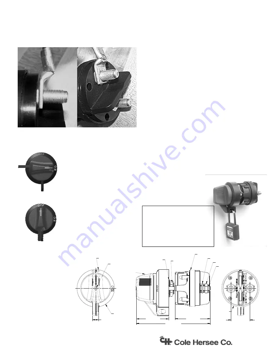
11. SEE PHOTO
Place the terminal(s) (attached to an appropriately sized
wire) directly on the base of the stud, as this will assure
the best contact and the least amount of voltage drop
across the connection.
12. Place lock washer over terminal and tighten down nut to
a torque of 70-90 in-lbs.
.
2.34 [59.5]
1.38 [34.9]
0.450 [11.43]
Ø2.75 [Ø69.8]
Ø2.72 [Ø69.1]
2.56 [65.0]
BEZEL, Black Plastic,
White Lettering (in kit)
HEX NUT,
Brass (in kit)
HOUSING, Black Plastic
LOCK WASHER
HEX NUT, Brass
STUD, Tin Plated Copper, 3/8-24
LOCKWASHER, (in kit)
CAP & SCREW, (in kit)
5.38 [136.7]
KNOB ASSY.,
(in kit)
Normal Operation Summary
General Specifications
IF-165
Rev B
Integral Lockout Feature!
Place a padlock or other lockout device
through both holes (the bezel and the
knob) and lock it. We recommend using
a locking device with a 5/16” or 7mm
shackle.
Environmental:
40ºC to 85ºC.
Sealed to IP67 per IEC 529
Ignition-proof
to
ISO
8846
Electrical:
Meets or exceeds UL 1107
Current Ratings
12V 300A continuous
24V
250A continuous
36V 200A continuous
Intermittent
1000A 90 secs On 5 minutes Off
1500A 60 secs On 5 minutes Off
2000A 30 secs On 5 minutes Off
3000A 15 secs On 5 minutes Off
Panel Thickness Range:
0.032-0.450” (0.81-11.43 mm)
Dimensions:
See
below
Submit technical questions to: [email protected]
Consult the factory if you need further assistance
617-268-2100
8:00am to 4:30pm Eastern Time
www.colehersee.com
ON
OFF
OFF:
Rotate the knob
90ºcounterclockwise until the indi-
cator is at the 12 o’clock position,
and the circuit will be
disengaged
ON:
Rotate the knob 90º clockwise
until the indicator is at the 3
o’clock position, and the circuit
will be engaged
Contents of 67191
Hardware Kit
1 Knob
Assembly
1
Knob Hole Plug
1 Bezel
1
4-40x0.75 Pan Head Screw
1
3/4” Lock Washer
2
3/4”-16 Hex Nuts
1-800-548-1191 - http://www.partdeal.com - [email protected]