Coiltek CS-5100 Series Скачать руководство пользователя страница 7


 Manual Set-Up 

 
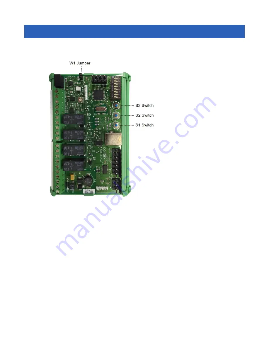
The CS-5000 is very easy to set up if the W1 jumper is in place.  Here's how: 


1.


Press button S1.  Lights above 
buttons S2 and S3 will begin 

to 

blink. 

2.


Put a target beneath the sensor 
(unless the product is very 
narrow, say <3/4” wide, use 
the material you're running).  
Place it in the position farthest 
from the sensor.  It will be the 
outer limit of your control 
range.  Press S3.  The light 
above S3 will stay on and stop 
blinking. 

3.


Place the same target at the 
desired near point of the 
control range.  Press S2.  If the 
set-up is accepted, the lights 
above S2 and S3 will go out 
and the system will return to 
run mode.  Calibration is 
complete. 


Alternately: 
 

1.


Press button S1.  Lights above buttons S2 and S3 will begin to blink. 

2.


Put a target beneath the sensor.  Place it in the desired near position.  It will be the upper 
limit of your control range.  Press S2.  The light above S2 will stay on and stop blinking. 

3.


Place the same target at the desired far point of the control range.  Press S3.  If the set-up is 
accepted, the lights above S2 and S3 will go out and the system will return to run mode.  
Calibration is complete. 

 
As shipped, after performing the procedure above, signal output will be 0VDC (4mA) at the far point 
and 10VDC (20mA) at the near point of the control range.  This output may be used to control 
upstream or process feeding devices.  In order to control downstream processes, the signal must be 
inverted.  To do this, turn on DIP switch #7.  If you remove jumper W1, your settings cannot be over-
written. 


Содержание CS-5100 Series

Страница 1: ...1 OPERATING MANUAL CS 5100 Series Controls 6676 Millersburg Road Wooster OH 44691 Tel 800 883 7542 330 601 1350 Fax 330 601 1352 Email info coiltek com Website www coiltek com...

Страница 2: ...Slack Loop Control 5 Manual Set Up 7 Extending Upper Limit 9 Offset 9 Remote Access to Presets 10 Terminals and Inputs 11 DIP Switch Functions 12 Cable Connections 14 Software and Sensitivity 15 Upgr...

Страница 3: ...sed to govern the speed of a follower device in the diagram it s a powered winder These controls may be programmed to control either upstream or downstream process followers Typical of upstream device...

Страница 4: ...includes a small 0 8W power supply as shown below The supply accepts any AC power source between 90 and 240VAC The supply requires only L1 and L2 Connect incoming ground to the subpanel or enclosure...

Страница 5: ...device to accelerate or decelerate In the diagrams above it s clear that the deeper U shaped loop develops the most free material between long and tight loop avoiding the generally undesired tight loo...

Страница 6: ...move over time Speed of Response Most slack loop control applications govern variable speed powered follower machinery When this is the case a well proportioned loop will yield better performance if...

Страница 7: ...ately 1 Press button S1 Lights above buttons S2 and S3 will begin to blink 2 Put a target beneath the sensor Place it in the desired near position It will be the upper limit of your control range Pres...

Страница 8: ...t keeping up If the full 10VDC or 20mA signal is required to synchronize the feeder with the process nuisance trips transpire To use this feature press the S2 and S3 buttons simultaneously The lights...

Страница 9: ...tton returning the unit to normal parameters Ensure that the lockout jumper W1 is in place before you attempt to use this feature Offset Offset bias is available and useful in some situations The grap...

Страница 10: ...ly the DIP switches are used for manual programming of the system Then they are all turned off and the remote switches or contacts access the presets via the header at P4 Since the DIP switches and th...

Страница 11: ...11 Terminals and Inputs...

Страница 12: ...ntrol of machinery that feeds a process such as a decoiler With SW7 ON the output is inverted such that 0V 4mA is generated at the near point of the control range and increases as the target draws awa...

Страница 13: ...dically This would also happen should the range card become disconnected The RED GREEN LED on the end of the sensor head mirrors the LEDs D2 and D3 red green It gives an immediate indication of the ta...

Страница 14: ...unit Range Card Endcap Features of the CB 5101R 2 Range Card This latest update of the Coiltek range card is form fit and function compatible with the CB 5101R CB 5101R 1 versions above All installati...

Страница 15: ...SB emulation As such a driver is included with the downloadable software CSWin32 Upon connection with the control Windows will recognize a new device It will query for a driver Choose to manually sele...

Страница 16: ...e new CB 5501M mainboard please note the following changes 1 The Reset button no longer functions The presets are immediately available using the 3 position selector switch which makes the Reset butto...

Страница 17: ...______________________________________________________________ ___________________________________________________________________________________ _____________________________________________________...

Отзывы: