9
6X-1086
3230 CAMERA
INSTALLATION MANUAL
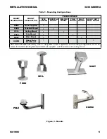
2. Ceiling mount (CEIL). This mounting arrangement
uses a ceiling mount arm to which the camera is
secured. See figure 3.
3. Pole Mount (POLE). When the camera must be
mounted to a pole this option provides both a clamp
to attach to the pole and also the heavy duty wall
mount (HDWM) on which to fasten the camera (See
figure 3).
4. Mast Mount (MAST). A mast mount attaches to
a horizontal arm using stainless steel straps. (See
figure 3.)
5. Heavy Duty Wall Mount (HDWM). This mounting
arrangement uses a wall mount arm designed for
rugged duty use (See figure 3).
The following paragraphs describe some of
the features of the 3230 related to the installation
process.
2.9 Installation Procedure
It is important to carefully plan for all cable
routing before starting an installation. In some situ
-
ations cable will have to be pulled through conduit
or other narrow places before adding a connector to
the end of a system cable. Any through-wall holes
may require weatherproofing.
Installing the 3230 is straightforward. It is only
necessary to mount the 3230 to a suitable base,
mate the cable connector to the system cable and
apply power. (Or connect to the camera with an
on-site cable.) This assumes the other end of the
cable is properly connected to a source of power, a
tv monitor, a graphical user interface (GUI), and any
other required equipment.
2.9.1 Camera Rear Panel Features
Three features on the rear panel are of interest
when installing the camera.
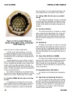
2.9.1.1 18-pin MS Connector
An 18-Pin MS connector on the rear panel
provides for all interconnections with the camera. A
mating plug kit is supplied for the system cable con
-
necting to this rear panel connector.
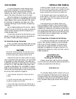
2.9.1.2 Schrader Valve
A Schrader valve (figure 7 — the car tire type
air valve on the left) on the rear panel provides for
pressurizing the housing with dry nitrogen. This
valve can be used to occasionally add dry nitrogen
as necessary to maintain pressure in the barrel at
about 5 psig (34 kPa). (Note: psig refers to pounds
square inch gauge — which designates pressure
relative to the altitude above sea level at which it is
being measured.)
2.9.1.3 Pressure Relief Valve
The pressure relief valve has a short piece of
clear tubing slipped around it to prevent acciden
-
tal movement of the pop out valve — which would
release nitrogen from inside the valve.
During shipping, at which times high altitude
might be encountered during aircraft transportation,
a pressure relief valve on the rear panel (figure 7)
may release some pressure. Back at low altitudes
this would be experienced as a housing pressure
below the standard 5 psig (34 kPa).
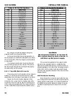
Table 3. Items Typically Requried but not
Supplied
ITEM
DESCRIPTION
CHARACTERIS-
TICS
1
Support Base
See figure 5
2
Cable
Power, RS-232 or RS-
422, 75-ohm Coax
3
Source of power
12 V dc, 24 V ac/dc, or
115 V ac, depending
on model
4
TV Monitor
75 ohm, NTSC or PAL,
as required
5
PC, Laptop, or oth
-
er control method
RS-232, RS-422 Serial
Output or converters
6
Serial Converte
r
232 / 422 converter
(see figure 6)
- end table -
Table 2. Items Supplied
ITEM
DESCRIPTION
CHARACTERIS-
TICS
1
Camera with sun
-
shield
Model 3230 series
2.
Connector Kit
1310230-011
Note: See figure 9 for the kit. This kit contains items to con
-
struct a cable plug that mates with the camera rear panel
connector.


