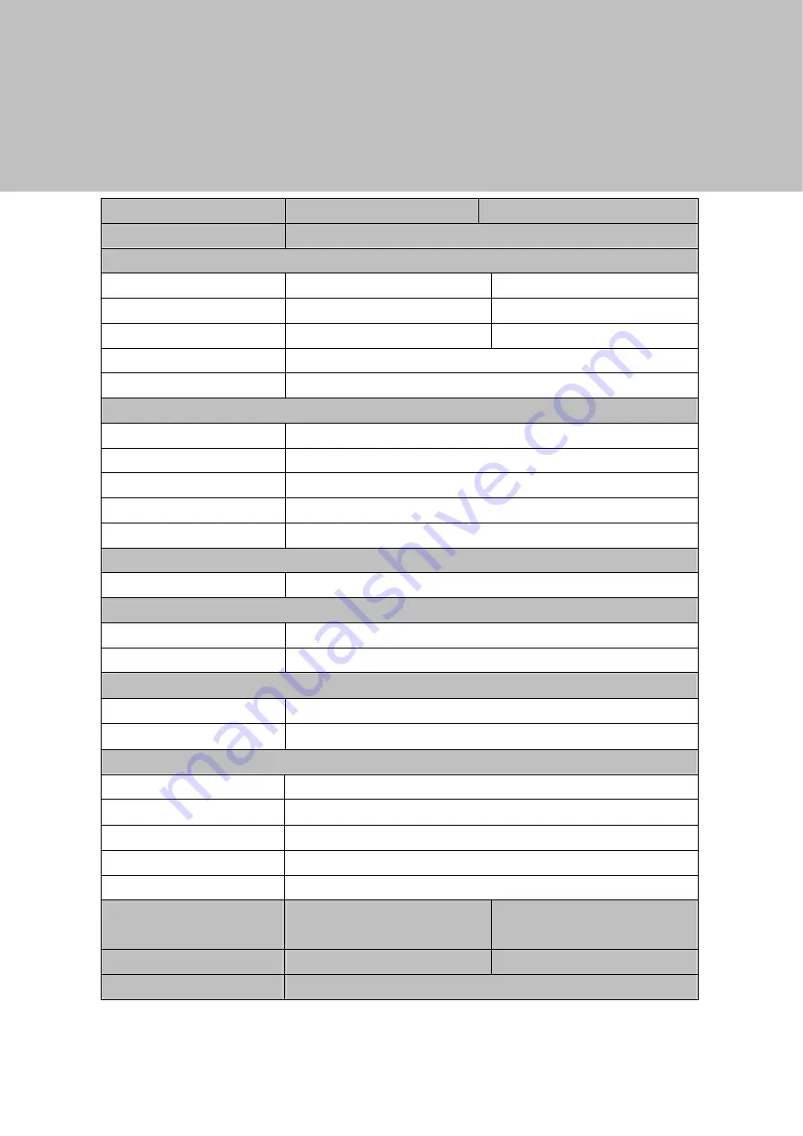
Code Soft EVO-TM2A Скачать руководство пользователя страница 20


14 

5  

Specification 


Model Name 

EVO-TM2A 

EVO-TM2B 

AD board 

B16 

LCD Panel   

Panel Size 

15"  

17"  

Brightness  

 250nits 

300~380nits 

Resolution 

  1024 x 768 

  1280 x 1024   

Touch  

Resistive    

Tilt Angle   

4° ~ 90°   

External I/O Ports   

USB   

1 x USB 2.0 (Type A), 1x USB 2.0 (Type B to PC) 

VGA 1 

Serial / COM   

2 x COM (1 x DB-9/F type to PC, 1 x RJ-45 type to VFD)

DC Jack 

OSD Button 

5 (left, right, power, menu, select) 

Power Adapter   

Power Source 

Ext. 36W, 12V / 3A   

Control / Indicator 

 Power Button 

 Indicator LED 

Peripheral 

MSR module 

MSR  (USB)  

Customer display 

2 x 20 VFD customer display (COM)   

Environment 

  EMC & Safety 

FCC/CE Class A, LVD 

 Operating Temperature 

0

o

C~ 40

o

C (32

o

F ~ 104

o

F) 

 Storage Temperature 

 -20

o

C ~ 55

o

C (-4

o

F ~ 131

o

F) 

  Operating Humidity 

5% to 95% RH, Non-condensing 

  Storage Humidity 

5% to 95% RH, Non-condensing 

Dimension  

(W x D x H) 

LCD 90 degree :   

365.2 x 217.8 x 338.9 mm

LCD 90 degree :   

399.2 x 217.8 x 381.5 mm

Weight (N.W./G.W.) 

4.8kgs / 5.8kgs 

6kgs / 7kgs 

Mounting 

100mm x100mm VESA Standard holes 

* This specification is subject to change without prior notice. 

Содержание EVO-TM2A

Страница 1: ...Revision v1 3 Dec 2010 EVO TM2A EVO TM2B Touch Screen Monitor User Manual...

Страница 2: ...or for incidental or consequential damages in connection with the furnishing performance or use of this material This document contains proprietary information that is protected by copyright All right...

Страница 3: ...should never be placed near or over a radiator or heat register or in a built in installation unless proper ventilation is provided 7 This product should be operated from the type of power indicated...

Страница 4: ...its working life Instead the device should be taken to the waste collection centers for activation of the treatment collection recycling and disposal procedure To prevent possible harm to the environ...

Страница 5: ...ion History Changes to the original user manual are listed below Revision Date Description V1 0 Sep 2009 Release V1 1 Oct 2009 MB version change V1 2 Aug 2010 MB version change V1 3 Dec 2010 Model nam...

Страница 6: ...tems 2 2 System View 3 2 1 Front View 3 2 2 Rear View 4 2 3 Bottom View 5 2 4 I O View 6 3 Peripheral Installation 7 3 1 MSR 7 3 2 VFD 8 3 3 Wall Mount Kit 10 4 System Assembly Disassembly 12 4 1 Remo...

Страница 7: ...the carton Remove the unit from the carton by holding it by the foam inserts The following contents should be found in the carton 1 1 Standard Items a d b e c f a Monitor b Driver CD c Power Adapter 3...

Страница 8: ...2 1 2 Optional Items a c b a MSR Module b VFD Module c Wall Mount Kit...

Страница 9: ...3 2 System View 2 1 Front View System Overview table 1 Number Component 1 Touch Screen 2 MSR Optional 3 OSD Button for OSD menu selection From left to right button 4 Stand Hole for cable management...

Страница 10: ...verview table 2 Number Component 5 VFD Module Optional 6 Stand with cable management and power adapter bracket 7 Cable Outlet 8 VFD Cover VFD module installation location 9 VESA hole for stand and wal...

Страница 11: ...5 2 3 Bottom View System Overview table 3 Number Component 9 Easy Service Retaining Bracket for Power Adapter 10 Rubber feet...

Страница 12: ...6 2 4 I O View System Overview table 4 Number Component a USB to Device b USB IN from PC c VGA IN d COM IN e COM 12V f 12V IN...

Страница 13: ...7 3 Peripheral Installation 3 1 MSR Components of MSR Kit 1 Slide the MSR into the right position of the System 2 Fasten the screws x2 and grounding cable x1 USB Grounding MSR Screws...

Страница 14: ...x2 and slide the VFD Cover outward 2 Position the VFD metal bracket onto the rear side of the VFD module and fasten the screws x4 3 Position the plastic bracket on the metal bracket as shown in the i...

Страница 15: ...e metal bracket and VFD module 5 Slide the VFD module with bracket into the VFD socket 6 Attach the VFD module by fastening the screws x2 as shown 7 Connect the VFD s RJ45 to the VFD Module 8 Connect...

Страница 16: ...unt Kit includes the following a Wall mount plate b Monitor mount plate screws c Screw metal bracket 2 The wall mount installs at the rear of the system 3 Attach part b to the back of the Touch Monito...

Страница 17: ...11 6 Mount part a to the wall in your desired location 7 Align the hooks of the monitor plate with the keyholes of the wall plate and slide the monitor into place 8 Tighten the thumb screw x1...

Страница 18: ...System Assembly Disassembly 4 1 Remove the System Stand 1 Remove the screws x2 that secure the stand to the system 2 Remove the screws x4 that secure the VESA mount to the monitor 3 Remove the VESA br...

Страница 19: ...13 4 2 Replace the Power Adapter 1 Release the thumb screw to seperate the retaining metal bracket from the stand and take out the power adapter...

Страница 20: ...t 36W 12V 3A Control Indicator Power Button 1 Indicator LED 1 Peripheral MSR module MSR USB Customer display 2 x 20 VFD customer display COM Environment EMC Safety FCC CE Class A LVD Operating Tempera...

Отзывы: