Code 3 21 COVERT Series Скачать руководство пользователя страница 2

Page 2 of 16

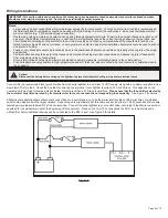
Installation & Mounting:

Mounting

Before proceeding with installation, plan all wiring and cable routing. Select the mounting location for the product on a flat, smooth surface 

and center the unit across the width of the vehicle. The mounting location should be chosen such that the product is level and visibility to 

approaching traffic is optimized.

Caution: 

When drilling into any vehicle surface, make sure that the area is free from any electrical wires, fuel lines, vehicle upholstery, vehicle 

support members, etc. that could be damaged.

Unpacking and Pre-Installation:

Carefully remove the product and place it on a flat surface. Examine the unit for transit damage and locate all parts. If damage is found or 

parts are missing, contact the transit company or Code 3. Do not use damaged or broken parts.

Ensure the product voltage is compatible with the planned installation.

Содержание 21 COVERT Series

Страница 1: ...signal Never take the right of way for granted It is your responsibility to be sure you can proceed safely before entering an intersection drive against traffic respond at a high rate of speed or walk...

Страница 2: ...raffic is optimized Caution When drilling into any vehicle surface make sure that the area is free from any electrical wires fuel lines vehicle upholstery vehicle support members etc that could be dam...

Страница 3: ...rved edge when possible as shown in FIGURE 2 4 With the mounting hardware positioned mark the location of the mounting hole centers on the roof of the vehicle Remove the lightbar and drill the mountin...

Страница 4: ...lightbar with the supplied washers and nuts as shown in FIGURE 3 5 With the mounting brackets positioned mark the locations of the mounting hole centers on the roof of the vehicle Remove the bar and d...

Страница 5: ...nto the gutter of the vehicles door frame as shown in FIGURE 4 3 Secure the feet to the lightbar in location by tightening the four 4 nuts on each foot 4 Slowly tighten the pan head screws to secure t...

Страница 6: ...ss of conductivity Ground termination should only be made to substantial chassis components preferably directly to the vehicle battery Circuit breakers are very sensitive to high temperatures and will...

Страница 7: ...stomer selected central node The following table indicates the default flash patterns of the serial lightbar These patterns are activated by other Matrix compatible products connected to the lightbar...

Страница 8: ...Class B 19 Double Flash 115 Class 1S Class 1S Class 1 Class 1 Class B 20 Double Flash 150 Class 1S Class 1S Class 1 Class 1 21 Triple Flash 60 Class 1S Class 1S Class 1 Class 1 Class B 22 Triple Flash...

Страница 9: ...uble Flash 75 Class 1S Class 1S Class 3S Class 1 Class 1 Class B 19 Double Flash 115 Class 1S Class 1S Class 3S Class 1 Class 1 Class B 20 Double Flash 150 Class 1S Class 1S Class 3S Class 1 Class 1 2...

Страница 10: ...power on demand to the light modules Max capacity is 15A RMS and up to 35A peak over the entire operating temperature range Caution Lightbar Controller outputs should only be connected to Matrix Comp...

Страница 11: ...pper Center 11 Lens Amber CZ2127U11A 21 27 Series Upper 22 5 Lens Amber CZ27U22A 21 27 Series Upper 22 5 Lens Blue CZ27U22B 21 27 Series Upper 22 5 Lens Black CZ27U22BLK 21 27 Series Upper 22 5 Lens C...

Страница 12: ...Center 8 Lens Black CR1608UBLA Covert Upper Center 8 Lens Blue CR1608UBLU Covert Lower Center 11 Lens Tint CR1611LSMK Covert Lower Center 11 Lens Clear CR1611LCLE Covert Upper Center 11 Lens Tint CR16...

Страница 13: ...21 Series Torus 3LED Blue Single Color CZ213B 21 Series Torus 3LED Red Single Color CZ213R 21 Series Torus 3LED White Single Color CZ213W 21 Series Torus 4LED Amber Single Color CZ214A 21 Series Toru...

Страница 14: ...18LED Red Amber Green Tri Color CZ2118RAG Covert 21 Series Torus 18LED Red Amber Green Tri Color CZ2118RAW Covert 21 Series Torus 18LED Red Blue Amber Tri Color CZ2118RBA Covert 21 Series Torus 18LED...

Страница 15: ...ular module should be in error flash mode Note that each light module is connected to the network with a black white twisted pair cable If any single connection point in the twisted pair sequence betw...

Страница 16: ...TIES FOR MERCHANTABILITY QUALITY OR FITNESS FOR A PARTICULAR PURPOSE OR ARISING FROM A COURSE OF DEALING USAGE OR TRADE PRACTICE ARE HEREBY EX CLUDED AND SHALL NOT APPLY TO THE PRODUCT AND ARE HEREBY...

Отзывы: