4350 Centennial Blvd. | Colorado Springs CO 80907 USA | 1-800-645-8862 |
3.125 Gbps Crosspoint Switch (XPS)
UT65CML8X8FD-EVB-UM Evaluation Board
4
/0
6
/2
0
2
2
U
SE
R
M
A
N
U
A
L
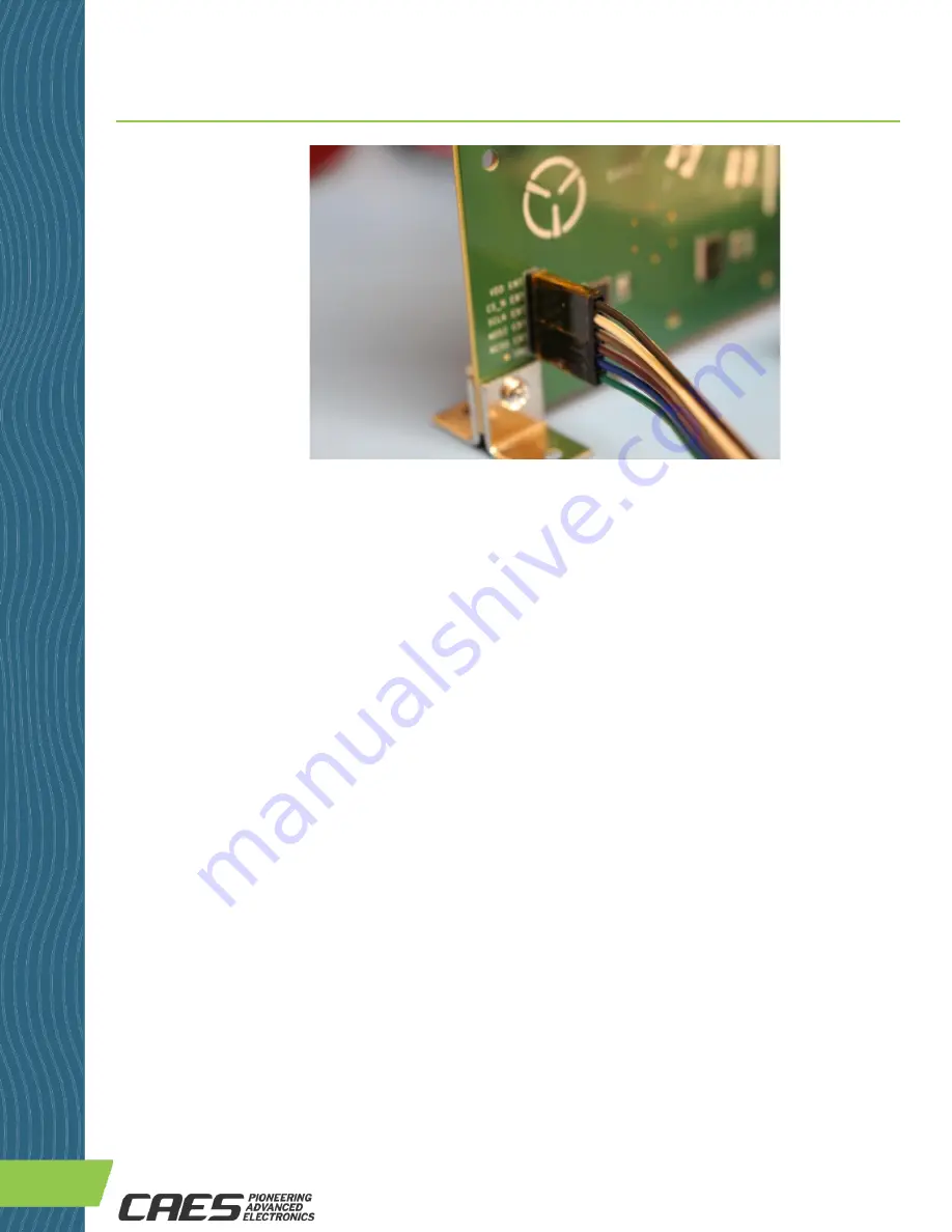
Figure 8: Close-up View of EVB Master SPI Port Cable Assembly Connector Interface
8b) Software (SW) Setup
The CAES UT65CML8X8FD-EVB XPS Evaluation Board Graphical User Interface (GUI) Software (SW) is required to
configure the XPS IC via the internal registers. See register description in the Register Map section of the data
sheet.
Installation instructions: Follow the installation instructions provided at website link to XPS SW GUI. Copy the
indicated files to the Windows PC computer that is intended to operate the GUI. Run the installer program. After a
successful GUI installation the GUI executable file “CAES XPS.exe” will be present in the run directory where the GUI
SW was installed. Double-click on this executable file to start the GUI. Click on the “Run” button as shown in
Figure 9. Set the PC device port for the NI USB-6501 USB-to-SPI Interface Device.
Once the GUI is operating, configure the XPS registers as required for your test configuration. Note that the XPS IC
will initialize in the default setting, per the Register Map, upon power-up. Always click on the “Run” button after re-
configuring the GUI settings to insure that the registers are updated with new data.
The recommended initial Receiver (RX) Equalization (EQ) setting is b’510101, or 0x15. This is different than the
power-up default setting of b’501000, or 0x08. See Table 10: SPI Port Register Map, p.18-19 of the data sheet.
The register names: EQ_<3:0>_<3:0>[4:0] and numbers: 0x04-0D are listed in the Register Map.


