( 5 )
5
PARA_NEO_BIFOLD_12/23/99
Trim Header Pieces
Before trimming Header pieces (b2 & b3), remember to add or
subtract any out of plumb discrepancies that might exist on the
corresponding walls (as measured at top of Wall Jambs)
.
Trim Header (B) pieces to measurements specified in step 1 (plus
or minus any out of plumb discrepancies).
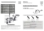
Assemble and Position Header atop Verticals
Assemble Header (B) by inserting Corner Brackets (R) into Header
pieces and bringing the pieces together (see figure above and
exploded view - sheet 3).
Using the Corner Bracket holes as guides, mark and drill the Header
pieces with a 1/8” drill bit. Secure the Corner Brackets to the Header
pieces with eight(8) #6 x 1/4” machine screws (S). Position Header
atop verticals.
Secure Header
From interior, secure both ends of Header to Wall Jambs using one
638PHPT Installation Screw (T) at each end. To prevent glass break-
age when drilling the Header, temporarily slide glass panel away
from Wall Jambs. When done, re-center glass panels as before.
TO PREVENT GLASS BREAKAGE
SLIDE GLASS PANELS AWAY FROM WALL JAMBS BEFORE DRILLING HEADER
Trim top & bottom Dam Strips
Measure the door opening width at Sill and Header levels. Trim top
and bottom Guide Tracks (C)to measurements obtained. With high
lips toward exterior, position Guide Tracks on the Header and Sill
and snap them into place.
I
nsert Glazin Vinyls
Insert Vertical and Horizontal Glazing Vinyl (V & W) to secure the
Glass Panels (U) in place. Use a vinyl roller to speed up installation.
Install Strike Jamb
Determine which side you want your door to strike (left or right, your
choice). Once strike side has been determined, insert Strike Post
(F) into the appropriate Corner Jamb (E), magnet should be facing
toward exterior of enclosure, see exploded view - sheet 3.
Install Top and Bottom Bushings
Before proceeding with Door
Assembly installation, note
that the Door Assembly (G)
must always fold in toward in-
terior of shower enclosure
(see exploded view - sheet
3).
Position Door Assembly on
floor the way it will be in-
stalled on enclosure (remem-
ber, unit must fold into enclosure).
Install Pivot Bushings (M), Pivot Bushing Screws (N) and Slide Piece
Set Screws (L) onto top and bottom Slide Pieces (g6) as shown in
figure above and in exploded view - sheet 3.
Содержание Paragon NEO ANGLE w/Bi-fold
Страница 3: ... 3 Paragon Neo Angle Bi Fold exploded view PARA_NEO_BIFOLD_12 23 99 ...
Страница 8: ... 8 ...