background image

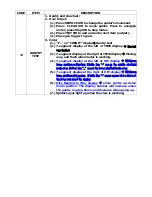
OUTPUT 
INTERFACE 

1.


Test output I/Os, including 4 items: 

2.


How to test: 

i.


Press SERVICE SW to change test items. 

ii.


Press TEST SW to quit for Sound Test. 

Display on PLAY Display on TIME display 


9 - 

Ticket dispenser Test 

1.


Left 7-segment display for ticket dispenser sensor. 

2.


Press the trigger to test ticket dispenser motor

.


1 0 

I/R receiver and transmitter Test 

1.


Spider’s eyes light up when I/R light is received. 

2.


Press gun trigger to test I/R light. Aim at spider target to 
check the receiver. 


1 1 

Counter Meter Test 

1.


10 units up in sequence 

2.


Explanation: 

7-segment display at the left of TIME 
7-segment display at the right of TIME 
 

1 X 

Coin 1 Meter 
Display in decreasing progressively


2 X 

Coin 2 Meter 

4 X 

Ticket dispenser Meter 


CODE ITEM 

DESCRIPTION 

Sound 

Test 

1.


Sound Test: 

2.


How to test: 

A.


Press SERVICE SW to change sound: 

B.


Press CLEAR SW to replay: 

C.


Press TEST SW to quit for “DISPLAY” item. 

3.


Explanation: 


'12'  displayed on the CREDIT display 


“Sound Test” code displayed on the TIME display 


Содержание SPIDER-BOT

Страница 1: ...Version W820 B16 Coastal Amusements Inc 1935 Swarthmore Ave Lakewood NJ 08701 732 905 6662 ...

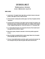
Страница 2: ...ccessfully hits the spider the Number of Hits Needed to Win display will decrease by 1 When the number is 0 the player wins 4 5 or 10 seconds before game over the game will send a bee sound to alert the player that time is about to expire 5 When time expires the spider will return to the home position upper left corner 6 When the player successfully hits the spider enough times to win the spider w...

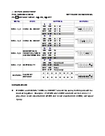
Страница 3: ...N 5 ON OFF 2 OFF ON 1 SW1 5 6 REDEMPTION TICKET S UPON COINS INSERTED OFF OFF 0 7 8 ON ON Very hard ON OFF Hard OFF ON Easy SW1 7 8 DIFFICULTY OFF OFF Very easy 1 2 3 4 5 6 7 8 DIP SW1 FACTORY DEFAULT X X X X X X O X EXPLAINATION If COIN1 and COIN2 s COIN vs CREDIT are set the same both inputs will be counted together Example If COIN1 and COIN2 are both set to 2 coins 1 play then 1 coin inserted i...

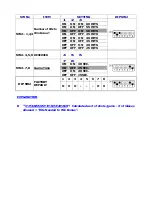
Страница 4: ...ITS OFF OFF ON 30 HITS SW2 1 2 3 Number of Hits to Win Bonus OFF OFF OFF 25 HITS SW2 4 5 6 RESERVED 4 5 6 7 8 ON ON 30 SEC ON OFF 25 SEC OFF ON 20 SEC SW2 7 8 Game Time OFF OFF 15SEC 1 2 3 4 5 6 7 8 DIP SW2 FACTORY DEFAULT O X O O X EXPLANATION HITS NEEDED TO WIN BONUS Calculated as of shots game of misses allowed Hits Needed to Win Bonus ...

Страница 5: ... ON OFF OFF OFF 9HITS 1TICKET OFF ON ON ON 8HITS 1TICKET OFF ON ON OFF 7HITS 1TICKET OFF ON OFF ON 6HITS 1TICKET OFF ON OFF OFF 5HITS 1TICKET OFF OFF ON ON 4HITS 1TICKET OFF OFF ON OFF 3HITS 1TICKET OFF OFF OFF ON 2HITS 1TICKET SW3 1 2 3 4 HITS TICKET OFF OFF OFF OFF 1HITS 1TICKET 5 6 ON ON 200 ON OFF 100 OFF ON 50 SW3 5 6 Bonus Reset Value OFF OFF 25 7 8 ON ON 4 TICKETS ON OFF 3 TICKETS OFF ON 2 ...

Страница 6: ...3 4 RESERVED OFF SW No ITEM SETTING DIP SW4 1 ON YES SW4 1 Keep CREDIT after power off OFF NO 2 ON YES SW4 2 Keep tickets owed after power off OFF NO 3 ON 10 SECONDS SW4 3 Bee sound ON before game time is up OFF 5 SECONDS 4 ON YES SW4 4 DEMO game OFF NO 5 ON Sound on SW4 5 Sound in attract OFF Sound on 6 ON SW4 6 Dispend unpaid tickets after power on OFF 7 ON YES SW4 7 Keep Progressive Bonus after...

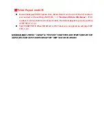
Страница 7: ...3 Number of Hits to Win Bonus If hit number is not reached to win bonus tickets the tickets payout is given by setting of DIP SW3 1 2 3 4 FLAT TICKET PAY When DIP SW4 8 is ON Tickets are only given by setting of DIP SW3 1 2 3 SYSTEM RESET PRESS CLEAR TEST SW TOGETHER AND THEN TURN ON THE GAME RELEASE BOTH SWITCHES AFTER BEE SOUND IS HEARD ...

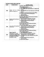
Страница 8: ... disconnected or faulty connection 2 Check if gantry JP1 harness pin disconnected 3 Main board failure E2 Lower stop SW breakdown on power up Press TEST SW for test mode and check The possible reasons 1 Lower stop SW breakdown harness disconnected or bad connection 2 Check if gantry JP1 harness pin disconnected 3 Main board failure E3 Upper stop SW breakdown on power up String is going down but up...

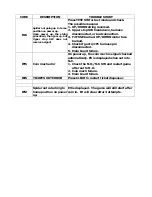
Страница 9: ...on 3 F2 FUSE burned UP DOWN motor fuse burned 4 Check if gantry JP1 harness pin disconnected 5 Main board failure E5 Coin mech error On power up the coin mech is signal checked automatically E5 is displayed when set into N C 1 Check the N O N C SW and restart game after set to N O 2 Coin mech failure 3 Main board failure E6 TICKETS OUT ERROR Press CLEAR to restart ticket dispenser E9 Spider not re...

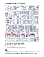
Страница 10: ...Up Down motors fuse 20mm slow 2A F3 Claw coil fuse 20mm slow 2A F4 Forward backward fuse 20mm slow2A TEST Press TEST SW for 0 8 seconds to enter test feature All motor power will shut down during test Press TEST SW to change test item and restart the game to quit TEST feature ...

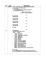
Страница 11: ...Test DIP SW4 SW4 ON OFF 5 Not Used 6 OTHER INPUTS KEY CODE displayed as below CODE Inputs 0 Coin Mech 1 1 Coin Mech 2 2 Ticket dispenser SENSOR 3 CLEAR SW 4 SERVICE SW 5 TEST SW 6 Not Used 7 Not Used 8 I R receiver SENSOR 11 Playfield UP SENSOR 12 Gantry UP Stop SW 13 gantry Down Stop SW 14 Gun trigger SW 16 Gantry right stop SW 17 Gantry left stop SW 18 Gantry up down home position plate sensor H...

Страница 12: ...y at the right of TIME display Moving way and flash when motor is working 4 7 segment display at the left of HIT display UP Down home position calibration Middle line means the middle playfield range over Bottom line _ means the lower playfield range over 5 7 segment display at the right of HIT display UP Down home position plate sensor Middle line means sensor status shows at the lower column of ...

Страница 13: ...ght is received 2 Press gun trigger to test I R light Aim at spider target to check the receiver 1 1 Counter Meter Test 1 10 units up in sequence 2 Explanation 7 segment display at the left of TIME 7 segment display at the right of TIME 1 X Coin 1 Meter Display in decreasing progressively 2 X Coin 2 Meter 4 X Ticket dispenser Meter CODE ITEM DESCRIPTION 5 Sound Test 1 Sound Test 2 How to test A Pr...

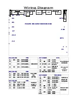
Страница 14: ...K B OK SENSOR SIGNAL 5 BE GND GND J8 COLOR PIN 6 BE WE GND GND DEMO CAPSULE HOME POSITION SENSOR 1 WE IN VR PIN1 2 RD OUT VR PIN2 J2 COLOR PIN RED 3 BK GND VR PIN3 VOLUMN VR 1K 1 OE M4 MOTOR 2 M4 MOTOR J3 COLOR PIN 3 GN M4 MOTOR 1 YW 12V 12V 4 M4 MOTOR CAPSULE DISPLAY SENSOR 2 BK GND GND 5 12V 12V 3 RD S5V 5V 6 BN 12V 12V 4 BK SGND GND POWER SUPPLY P2040 PIN 7 BK B SEN PRIZE OUT MOTOR 8 W SEN 9 BE...

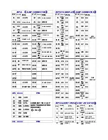
Страница 15: ... RD CM1 CREDIT DISPLAY 20 PK CM3 HITS DISPLAY 21 PE CLEAR SW 22 BK GND 21 BN CA 22 RD WE DA 23 GY SERVICE SW 24 GND 23 RD CB 24 OE WE DB 25 PK TEST SW 26 GND 25 OE CC 26 YW GN DC 27 28 27 YW CD 28 GN WE DD 29 30 29 GN CE 30 BE WE DE 31 12V 32 START LIGHT 31 BE CF 32 PE WE DF 33 START SW 34 GND 33 PE CG 34 GY B K DG 35 36 J6 COLOR PIN 37 GY CM4 38 WE BE CM6 1 RD 12V 39 WE CM5 LASER POWER DISPLAY 40...

Страница 16: ...K UP STOP SW N O 10 BK DOWN STOP SW N C 4 GR 24V 24V 11 TOP SW 12 GND 5 BK GND GND POWER SUPPLY P2040 PIN 13 BN 24V 14 GN CLAW 15 16 YW BK DATA 17 GN RD CLK 18 PE Y W LASER IN 19 BE GND 20 BE O E LATCH 13 20 CONNECT TO J1 OF W060102 ...

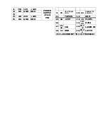
Страница 17: ...ND 10 WE CM9 CONNECT TO HITSNEEDED TO WIN DISPLAY 10 LED W 11 12V 12 12V J12 COLOR PIN J13 COLOR PIN 1 BN TX 1 BN AC1 2 BK GND 2 BE AC2 TRANSFORMER AC12V 3 OE RX 4 GND CONNECT TO J3 OF MATRIX BOARD W040314 J14 COLOR PIN J15 COLOR PIN 1 BN AC2 1 BN AC2 2 RD LED11 2 RD LED11 3 OE LED12 3 OE LED12 4 YW LED13 4 YW LED13 5 GN LED14 5 GN LED14 6 BE LED15 6 BE LED15 7 PE AC2 CONNECT TO ROUND LED BOARD W0...

Страница 18: ...4 YW BK DATA 5 GN RD CLK J1 COLOR PIN 6 BE OE LATCH 1 RD 12V 7 PE YW LASER CONNECT TO J2 PIN 13 29 OF W060101 2 OE MOT 3 YW CLT J2 COLOR PIN 4 GN LED1 1 GN CLAW CLAW COIL 5 BE LED2 2 WE 24V CLAW COIL 6 PE SW 7 BK GND CONNECT TO J6 OF W060101 J3 COLOR PIN 1 BE EYE LED1 J2 COLOR PIN 2 GN EYE LED2 1 PK LED I R LED 3 YW 5V CONNECT TO W060102A 1 2 BK LED I R LED J5 COLOR PIN J4 COLOR PIN 1 PK Ball LED1...

Страница 19: ... J3 1 1 1 J1 COLOR PIN NOTE J3 COLOR PIN NOTE 1 YW 12V INPUT 1 2 BK GND 12V GND 2 3 RD 5V INPUT 3 4 BK GND 5V GND POWER SUPPLY PIN 4 5 J2 COLOR PIN NOTE 6 NOT USED 1 BN TX 2 BK GND 3 OE RX CONNECT TO J12 OF W060101B SW1 U15 U9 ROM ...

Отзывы: