


11
3-3-2 CSOF-S8PL(H), CSOF-S10PL(H)
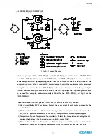
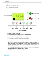
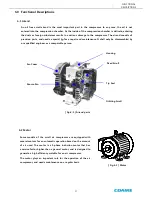
[ Fig.3-8 ] System Diagram
The basic principle of the CSOF-S8PL(H) and CSOF-S10PL(H) is equal to that of CSOF-M3PL(H)
and CSOF-M5PL(H). However, the CSOF-S8PL(H) and CSOF-S10PL(H) have two airends to
sequentially be started up depending on the load to be used. As there is no air tank in the
compressor, a drain valve is used on the discharge end to drain the condensate water generated
during the compression. For the CSOF-S8PL(H) or above, an air receiver tank shall separately be
ordered and installed by the amount of air used. The tank capacity varies depending on the load
to be used, for example, minimum capacity is 16gal for the CSOF-S8PL(H), and 21gal for the
CSOF-S10PL(H).
There are following four safeguards in CSOF-S8PL(H) and CSOF-S10PL(H) models:
1)
Over Current Relay (OCR) for Motor – Detects the over current of each motor to stop only the
motor failed.
2)
Mechanical Safety Valve – Mechanically discharges the compressed air in the air tank to the
air, if the air pressure exceeds the set value. The compressor shall manually be stopped.
3)
Temperature Sensor (Temperature Transmitter ) – Detects the temperature exceeding the set
value at the bottom of each airend to stop only the motor failed.
4)
Pressure Sensor (Pressure Transmitter ) – Detects the pressure in the air tank and sends the
value to the controller to stop the compressor, if the air pressure exceeds the set value.
GENERAL