


MAN. 161 rev. 5 Use and maintenance manual Sup15
12ª
page of
77
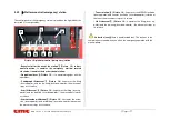
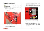
2.3.1
Frame
1
(
Picture 5
)
Quality steel structure able to equally divide the equipment’s weight when
the MEWP is in transport position. The frame has 4 oil-pressure jack arms
for stabilization [2 front stabilizer cylinders 2 (Picture 5), 2 rear stabilizer
cylinders 3 (Picture 5)]. The basis for the bearing is placed on the frame 4
(Picture 5), it enables the swinging of the equipment through the rotation
group.
2.3.2
Turret
5 (Picture 5)
The turret, in quality steel, is fixed on the bearing. It is started by a hydraulic
engine (whose brake is normally closed), placed inside the turret. It enables
the rotation of the superstructure.
2.3.3
Double Pantograph
6 (Picture 5)
The pantograph is composed by two couples of parallel arms
(Picture 5)
and by the pantograph connecting rod
7
. The arms (tubular with rectangu-
lar section, press-formed and electro welded) and the connecting rod are in
quality steel sheets.
The movement of the pantograph (pantograph lifting
and descent)
is realized by the pantograph lifting oil-pressure cylinder. This
cylinder is hinged to the turret
(rod side) and to the pantograph upper crank
(stem side) and it has a double effect balancing valve This cylinder is
hinged to the turret.
2.3.4
Telescopic arm
8 (Picture 5)
The telescopic arm is hinged to the turret 8 (Picture 5). The telescopic arm
is composed by two elements: 1 fixed arm, hinged to the pantograph con-
necting rod, and 1 sliding arm.
The sliding or re-entry movement of the telescopic arm is activated by op-
erating the “telescopic arm sliding cylinder device”.
The lifting or descend movement of the telescopic arm is activated by op-
erating the “telescopic arm lifting cylinder device”.
2.3.5
Jib
9 (Picture 5)
At the end of the telescopic arm is hinged an arm named Jib. The lifting or
descent of the Jib is done by operating the “Jib lifting cylinder” 10 (Picture
5).
2.3.6
Basket
11 (Picture 5)
In aluminium tubular, it has a lateral opening to allow the entrance of the
operators. The lateral opening is an auto-shutter and built to avoid acci-
dental openings. The basket has strong points for safety belts, a guard-rail
1,1m high from the basket floor, an intermediate guard-rail and a foot pro-
tecting band along all sides of the platform. The floor is in antiskid and au-
to-draining aluminium. The basket is removable: it is connected to a sup-
port through which it is possible to couple it with the jib.
Содержание SUP15
Страница 8: ...MAN 161 rev 5 Use and maintenance manual Sup15 8ª page of 77 Picture 4 stabilization area mm ...
Страница 21: ...MAN 161 rev 5 Use and maintenance manual Sup15 21ª page of 77 Picture 12 basket joint pin and splint pin ...
Страница 70: ...MAN 161 rev 5 Use and maintenance manual Sup15 70ª page of 77 10 10 Notes ...
Страница 71: ...MAN 161 rev 5 Use and maintenance manual Sup15 71ª page of 77 10 11 Maintenance of tracked undercarria ges ...
Страница 72: ...MAN 161 rev 5 Use and maintenance manual Sup15 72ª page of 77 ...
Страница 73: ...MAN 161 rev 5 Use and maintenance manual Sup15 73ª page of 77 ...
Страница 74: ...MAN 161 rev 5 Use and maintenance manual Sup15 74ª page of 77 ...
Страница 75: ...MAN 161 rev 5 Use and maintenance manual Sup15 75ª page of 77 ...
Страница 76: ...MAN 161 rev 5 Use and maintenance manual Sup15 76ª page of 77 ...


