15
Charger Repairs
BATTERY CHARGER
TEST PROCEDURE 4 – AC Power and Continuity Test of AC Circuit
1.
Disconnect AC cord from the wall outlet and DC plug from the vehicle receptacle.
2.
Check the AC line fuse or circuit breaker in the storage facility.
3.
With a multimeter set to 500 volts AC, check incoming AC voltage. Insert multimeter test probes into AC wall
outlet; voltage should be between 85 and 270 volts.
See QuiQ Battery Charger Specifications, Section 2,
If proper voltage is not present, have building wiring checked by a licensed electrical contractor.
4.
If the charger will not power ON, check AC cord connections.
5.
If the charger is connected correctly, check continuity of the AC cord wires.
TEST PROCEDURE 5 – Charger DC Circuit Continuity Test
1.
Disconnect the AC cord from the wall outlet and the DC cord plug from the charger lead.
2.
Check continuity of the DC cord wires from plug pin to large solenoid post (10-gauge red wire) and B- terminal of
controller (10-gauge black wire).
See following NOTE.
NOTE:
The 10-gauge red wire from the charger to the solenoid has an in-line 30-amp fuse.
3.
When finished, connect DC cord plug to the charger lead.
CHARGER REPAIRS
See General Warnings on page 1-2.
NOTE:
The high frequency charger offers no replacement parts. If necessary, the charger must be replaced.
Onboard Charger Removal And Installation on page 15-12.
ONBOARD CHARGER REMOVAL AND INSTALLATION
See General Warnings on page 1-2.
WARNING
• Knowledge of battery charger wiring and component terminology is required before attempting any
repair See Troubleshooting on page 15-10.
• Prior to servicing the charger, disconnect the AC power supply cord from the wall outlet and remove
the battery charger from the vehicle.
ONBOARD CHARGER REMOVAL
1.
Disconnect the batteries and discharge the controller.
See Disconnecting the Batteries – Electric Vehicles,
2.
Remove the wire ties securing the connector to the charger P-clip.
3.
Disconnect the all connectors from the charger AC and DC connector.
4.
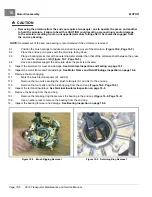
Remove four lock nuts (5) securing charger to charger mounting plate.
Page 15-12
2019 Transporter Maintenance and Service Manual
Содержание TransPorter 4
Страница 2: ......
Страница 18: ...Pagination Page 1 General Warnings SAFETY Page 1 6 2019 Transporter Maintenance and Service Manual ...
Страница 112: ...8 Tires WHEELS AND TIRES Figure 8 2 Inflate Tire Page 8 4 2019 Transporter Maintenance and Service Manual ...
Страница 271: ...ELECTRIC MAIN HARNESS Wiring Diagrams Electric Main Harness 18 ...
Страница 272: ... Page intentionally left blank ...
Страница 273: ...ELECTRIC INSTRUMENT PANEL HARNESS Wiring Diagrams Electric Instrument Panel Harness 18 ...
Страница 274: ... Page intentionally left blank ...
Страница 275: ...ELECTRIC ACCESSORIES HARNESS Wiring Diagrams Electric Accessories Harness 18 ...
Страница 276: ... Page intentionally left blank ...
Страница 282: ...NOTES ...
Страница 283: ...NOTES ...
Страница 284: ...NOTES ...
Страница 285: ......
Страница 286: ......

