12
Test Procedures
ELECTRICAL SYSTEM TROUBLESHOOTING
TEST PROCEDURE 4 – Fuses
See General Warnings on page 1-2.
WARNING
• Failure to use properly rated fuse can result in a fire hazard.
NOTE:
These vehicles predominately use a combination of ATC-style and ATM-style blade fuses. A single AGC-style
glass fuse is used for the charger interlock circuit.
This is a voltage test. It can be performed relatively easily on ATC-style and ATM-style fuses. A voltage
test can be performed on the AGC-style glass fuse if insulation-piercing probes are used. Otherwise, the
AGC-style will have to be removed to visually inspect or check using a continuity test.
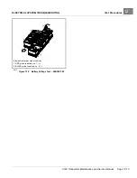
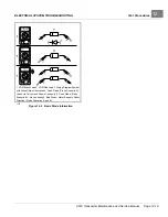
2976
Figure 12-5
Testing the Fuse
1.
If necessary, see Testing Basics on page 12-11.
2.
Access the fuses but do not remove them. Fuses are found at the following locations:
–
On Controller Mounting Plate:
15-amp fuse to DC/DC converter, 2-amp fuse to connected car device
(Guardian/Visage V3 Circuit), and 15-amp fuse to electric powertrain
–
Under Floorboard Near MCOR:
20-amp fuse from DC/DC converter to accessories
–
Under Front Cowl:
15-amp fuse to cab, 10-amp fuse to brake lights, horn and turn signals, 7.5-amp fuse to
headlights and taillights, 10-amp fuse to 12-volt power strip and power point
–
On Main Harness Near Controller Mounting Plate:
30-amp fuse for charger receptacle harness
–
On Main Harness Forward of the 30-Amp Fuse:
1-amp fuse for charger interlock circuit
3.
2-Amp and 15-Amp ATC Fuses On Controller Mounting Plate and 30-Amp ATC Charger Receptacle Fuse:
With the batteries connected and the Run/Tow switch in the RUN position:
3.1.
Probe the two, small metal contacts on the top of the fuse
3.2.
Each contact should show BPV.
3.3.
If only one side shows BPV, replace fuse.
3.4.
If neither side of fuse shows BPV, do the following:
– Check BPV.
– Check condition and connection of large red wires at solenoid.
– Check sonic weld_8 in main wire harness.
Page 12-16
2019 Transporter Maintenance and Service Manual
Содержание TransPorter 4
Страница 2: ......
Страница 18: ...Pagination Page 1 General Warnings SAFETY Page 1 6 2019 Transporter Maintenance and Service Manual ...
Страница 112: ...8 Tires WHEELS AND TIRES Figure 8 2 Inflate Tire Page 8 4 2019 Transporter Maintenance and Service Manual ...
Страница 271: ...ELECTRIC MAIN HARNESS Wiring Diagrams Electric Main Harness 18 ...
Страница 272: ... Page intentionally left blank ...
Страница 273: ...ELECTRIC INSTRUMENT PANEL HARNESS Wiring Diagrams Electric Instrument Panel Harness 18 ...
Страница 274: ... Page intentionally left blank ...
Страница 275: ...ELECTRIC ACCESSORIES HARNESS Wiring Diagrams Electric Accessories Harness 18 ...
Страница 276: ... Page intentionally left blank ...
Страница 282: ...NOTES ...
Страница 283: ...NOTES ...
Страница 284: ...NOTES ...
Страница 285: ......
Страница 286: ......


