background image

Controls and Indicators – Electric Vehicles

FORWARD/REVERSE CONTROL

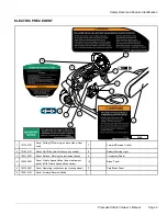
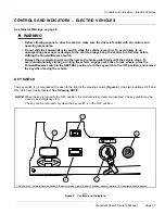
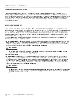
The Forward/Reverse rocker switch (2) is mounted on the dash below the steering column

(Figure 6)

. The

F

(FORWARD) and

R

(REVERSE) are clearly marked. Push down the FORWARD side of the switch to operate the

vehicle in the forward direction, or push down the REVERSE side of the switch to operate the vehicle in reverse. When
the rocker switch is positioned in the NEUTRAL position, with neither side down, the vehicle will not operate if the
accelerator pedal is pressed. The reverse buzzer will sound as a warning when the Forward/Reverse switch is in
the REVERSE position.

ACCELERATOR PEDAL

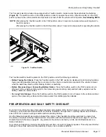
The accelerator pedal is the pedal on the right, with the word GO molded into it

(Figure 7)

. The operation of the

accelerator pedal differs from that of an automobile. When the key switch is the ON position, and the Forward/Reverse
switch is in either the FORWARD or REVERSE position, pressing the accelerator pedal will automatically release
the park brake and start the vehicle moving in the direction selected (forward or reverse). As the accelerator pedal
is pressed, speed will increase until full speed is reached. When the accelerator is released, power will be cut off
and the motor will stop running.

Electric vehicles use a special electrical system, which employs motor braking in some modes of operation. In
those modes, the vehicle operates as follows:

Walk Away Braking:

This feature prevents the vehicle from rolling away uncontrolled should the driver park on a

slope and leave the vehicle without locking the park brake. The vehicle will roll at about 1 mph (1.6 km/h). If the
walk away braking function remains engaged for two seconds or more, a warning buzzer will sound to alert the
driver that motor braking has been activated.

See following WARNING.

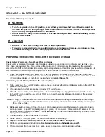
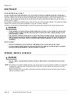
WARNING

• Walk away braking will not limit vehicle speed to 1 mph (1.6 km/h) on very steep grades. Do not

operate vehicle on slopes exceeding 20% grades.

Excel System Vehicles

Motor Braking:

This feature helps to control vehicle downhill speed. When traveling downhill, motor braking

engages to maintain speeds proportional to the accelerator pedal position. For example, when the accelerator is
fully pressed, motor braking holds the vehicle at the programmed top speed. When the accelerator pedal is fully
released, motor braking slows the vehicle to a complete stop or allows the vehicle to coast freely, depending
upon the selected controller setting. This feature is selectable. Contact your local Club Car dealer/distributor to
inquire about this feature.

See following WARNING.

WARNING

• When batteries are fully charged, a warning buzzer will sound during motor braking to alert the driver

that motor braking is operating at a reduced level of performance. When this occurs, use the brake
pedal to control vehicle speed.

Page 14

Precedent Stretch Owner’s Manual

Содержание Precedent Stretch

Страница 1: ...Precedent Stretch Owner s Manual Electric Refer to back cover for applicable build code range...

Страница 2: ......

Страница 3: ...ay be photocopied reproduced or translated to another language without the written consent of Club Car LLC The information contained in this document is subject to change without notice Club Car reser...

Страница 4: ...ub Car dealer or distributor who will be able to provide technical advice perform warranty work and sell parts and service manuals For the name and address of the authorized Club Car dealer or distrib...

Страница 5: ...c Vehicles 13 Pre Operation and Daily Safety Checklist 17 Driving Instructions 19 Transporting on a Trailer 21 Storage Electric Vehicle 22 Maintenance 24 Periodic Service Schedule 24 Periodic Lubricat...

Страница 6: ...Y DECAL AND FEATURE IDENTIFICATION The following pages contain safety decal and feature identification information For detailed information on specific features read the appropriate section in this ma...

Страница 7: ...Off Key Switch above key switch 8 Battery Warning Light 3 102519301 Decal Rollover Warning on instrument panel 9 Accelerator Pedal 4 102555901 Decal Private Speed Notice below instrument panel With Pr...

Страница 8: ...Tag SPWS Battery Warning on battery watering tubes with Single Point Watering System option 4 103384801 Decal Tow Run Warning 2 103384601 Decal Water Exposure Caution 5 Tow Run Switch 3 103384701 Dec...

Страница 9: ...ormation in this manual Understand and become familiar with the DANGER WARNING and CAUTION statements and procedures it contains along with the safety decals that are affixed to your vehicle Take time...

Страница 10: ...CAUTION with the safety alert symbol indicates a hazard or unsafe practice that could result in minor personal injury CAUTION A CAUTION without the safety alert symbol indicates a potentially hazardo...

Страница 11: ...ncreases maximum vehicle speed beyond factory specifications could result in severe personal injury or death Check the vehicle for proper location of all vehicle safety and operation decals and make s...

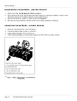
Страница 12: ...to discharge CONNECTING THE BATTERIES ELECTRIC VEHICLES 1 Ensure the Tow Run switch is in the TOW position 2 Connect the battery cables positive cable first 3 Tighten battery terminals to 110 in lb 1...

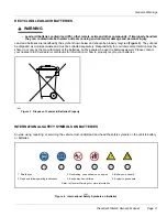
Страница 13: ...batteries but by people who use the batteries as well Please contact your nearest Club Car dealer or distributor for information on how to properly recycle your batteries 1403 Figure 3 Dispose of Lea...

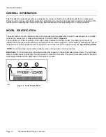
Страница 14: ...the serial number indicate the vehicle model The following four digits 2 indicate the model year and production week during which the vehicle was built The six digits 3 following the hyphen represent...

Страница 15: ...r rolling the vehicle engage park brake to lock wheels place the Forward Reverse switch in the NEUTRAL position turn the key switch to the OFF position and remove the key when leaving the vehicle KEY...

Страница 16: ...in some modes of operation In those modes the vehicle operates as follows Walk Away Braking This feature prevents the vehicle from rolling away uncontrolled should the driver park on a slope and leav...

Страница 17: ...ith your foot Figure 8 78 Figure 8 Brake Pedal 79 Figure 9 Park Brake Pedal PARK BRAKE PEDAL The park brake pedal is the small raised portion in the upper left corner of the brake pedal It has the wor...

Страница 18: ...s The warning light will not illuminate if the charge is 90 or more complete The onboard computer will retain in memory the amount of charge needed to fully replenish the batteries and will complete t...

Страница 19: ...ch in the TOW position to turn off power to the vehicle electrical system thus preventing severe arcing and possible battery explosion as the battery cables are disconnected For Long Term Storage Plac...

Страница 20: ...ps abruptly or makes a grinding or squeaking noise have the brake system checked and adjusted as required Continued moderate brake pedal pressure should be able to lock the wheels but using lesser pre...

Страница 21: ...ot specially equipped for handicapped persons Be sure all persons can properly operate the vehicle prior to allowing them to drive the vehicle Be sure all passengers are capable of securing themselves...

Страница 22: ...key to the ON position and make sure nothing is in your path 6 Select direction by placing Forward Reverse handle or switch in desired position F forward or R reverse A buzzer will sound as a warning...

Страница 23: ...irements such as taillights brake lights etc Do not tow a Club Car vehicle behind a passenger vehicle or truck on a public road unless it is on an approved trailer The vehicle to be towed should be ti...

Страница 24: ...Electrolyte level should be from inch 13 mm above plates to inch 6 mm below the level indicator Figure 12 Immediately Prior to Storage Perform the Following Steps 1 Turn the key switch to the OFF pos...

Страница 25: ...lable electrolyte it will stop the charger from further operation Disconnecting then reconnecting the DC cord stationary charger or AC cord onboard charger indicates the electrolyte levels have been m...

Страница 26: ...y repairs could result in fire property damage severe personal injury or death Only trained technicians should service or repair the vehicle or battery charger Anyone doing even simple repairs or serv...

Страница 27: ...ner or trained technician General Vehicles Thoroughly wash vehicle including the underside Initial one time inspection by owner or trained technician after six weeks of use Batteries For vehicles newl...

Страница 28: ...27 Annual service by trained technician only or every 100 hours of operation whichever comes first General Vehicle Check for loose hardware tighten if necessary Refer to the appropriate maintenance a...

Страница 29: ...2 Semiannually by owner or trained technician or every 50 hours of operation whichever comes first Front suspension two fittings Chassis Lube EP NLGI Grade 2 Check fill transaxle to plug level 22 oz 0...

Страница 30: ...nd require water to be added periodically Automotive batteries should never be used in electric vehicles New batteries will not deliver their full capabilities until they have been discharged and rech...

Страница 31: ...WABLE CONTENT PARTS PER MILLION EFFECTS OF IMPURITY Suspended matter Trace Total solids 100 0 Organic and volatile matter 50 0 Corrosion of positive plates Ammonia 8 0 Slight self discharge of both pl...

Страница 32: ...tery case For 8 volt batteries tighten hold down retaining nuts to 106 in lb 12 N m The terminal connections should be clean and tight and any worn insulation or frayed wires should be replaced Tighte...

Страница 33: ...interval See Establishing the Watering Interval for New Vehicles on page 31 See Watering Batteries with the SPWS on page 32 CAUTION The watering interval must adequately maintain the electrolyte level...

Страница 34: ...the purger 5 to the female coupler 8 on the end of the hose end assembly Figure 14 1 2 3 5 4 5 7 6 8 3 68 Figure 13 Connecting Hose with Filter to Water Source 69 Figure 14 Checking the Water Flow Rat...

Страница 35: ...ill coupling and call for service 3 When the red flow indicator balls stop moving immediately press the grey button to disconnect the hose end assembly from the battery fill coupling 9 and squeeze the...

Страница 36: ...th proper cleaning Use a solution of 10 liquid soap and warm water applied with a soft cloth For imbedded dirt a soft bristle brush may be used For heavy soiling difficult stains or scratches blemishe...

Страница 37: ...rake BODY CHASSIS Frame Chassis Aluminum and composite Front and rear body Dupont Surlyn Reflections Body finish High gloss molded in color Tires 18 x 8 5 8 tubeless 4 ply rated DIMENSIONS WEIGHT Over...

Страница 38: ...d rear 18 20 psi 1 24 1 38 bars NOISE AND VIBRATION Drive by noise level to operator Test method EN 12053 2001 68 5 dBA Uncertainty 2 dBA Vibration at driver s seat Test method EN 13059 2002 0 8 m s2...

Страница 39: ...Warranty WARRANTY TBD Precedent Stretch Owner s Manual Page 37...

Страница 40: ......

Страница 41: ...erprufung Normes Utilisee pour Verification Normas Usado por Comprobacion Waarden Aangewend voor Verificatie Modelos Utilizado para Verifcacao Standard per la Verifica Standarder Anvendte Nemlig Efter...

Страница 42: ......

Страница 43: ......

Страница 44: ......

Страница 45: ...Club Car R NOTES...

Страница 46: ......

Страница 47: ......

Страница 48: ...Publication Part Number 103897206 Edition Code 1111B1111A 103897206 This manual is valid for vehicles with build codes between 55137 and the one indicated at the top of this page...

Отзывы: