background image

STEERING AND FRONT SUSPENSION

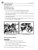
Rack and Pinion

Page 7-12    2001 Pioneer 900 Gasoline Vehicle Maintenance and Service Manual

7

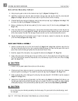
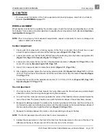
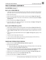
Rack and Pinion Assembly, Continued:

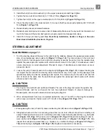
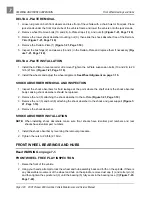
10. Place a few drops of Loctite

®

 222 to the threads of the screw (16) (Figure 7-12, Page 7-11).

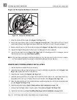
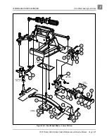
11. Install the rack guide (13), pressure spring (14), and screw (16). The screw should be threaded in until

a rotational torque of 10 in-lb (1.13 N·m) is achieved (Figure 7-12, Page 7-11).

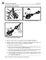
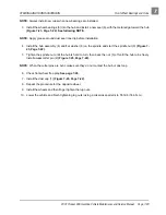
11.1. Reposition the rack and pinion in a vise.

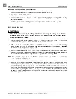
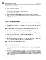
11.2. Insert a 3/8 inch deep well socket into the steering column end of the universal joint (2) and

tighten the bolt (1) to 15 ft-lb (20.3 N·m) (Figure 7-15, Page 7-12).

11.3. Use a torque wrench connected to the 3/8 inch deep well socket to measure the resistance of the

rack and pinion. Rotational resistance should measure 7 to 15 in-lb (.8 to 1.7 N·m).

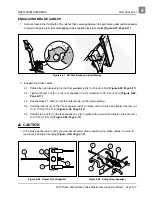
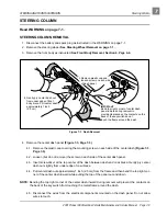
11.4. If measured resistance does not equal 7 to 15 in-lb, loosen the lock nut (15) and tighten the screw

(16) until it bottoms out, then back the screw off one quarter turn. Tighten the lock nut to 28 ft-lb
(38 N·m) (Figure 7-14, Page 7-12).

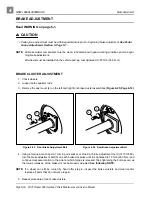
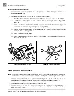
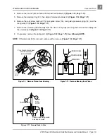
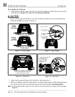
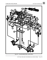
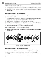
Figure 7-13   Press In Dust Seal

Figure 7-14   Rack and Pinion Adjustment

Figure 7-15   Rack and Pinion Resistance

DUST SEAL

15/16 DEEP WELL
SOCKET 

16

15

2

25

VISE

3/8 INCH

1/4 DRIVE

DEEP WELL

SOCKET

1

Содержание Pioneer 900

Страница 1: ......

Страница 2: ......

Страница 3: ...b Car advises that all repairs and or service be performed by an authorized Club Car distributor dealer representative or by a Club Car factory trained technician It is the policy of Club Car Inc to a...

Страница 4: ...future editions of this manual Damage to a vehicle or component thereof not resulting from a defect or that occurs due to unrea sonable or unintended use overloading abuse or neglect including failur...

Страница 5: ...he Vehicle 4 1 Front Body Repair 4 2 Stress Lines or Streaks 4 2 Minor Impact Damage Deformations 4 2 Minor Scratches and Surface Blemishes 4 3 Small Scratches that Cannot be Buffed out 4 3 Gouges Pun...

Страница 6: ...Park Brake Installation 5 4 Accelerator Pedal 5 5 Accelerator Pedal Removal 5 5 Accelerator Pedal Installation 5 6 Pedal Group Adjustment 5 7 SECTION 6 WHEEL BRAKE ASSEMBLIES General Information 6 1 B...

Страница 7: ...Removal 7 8 Rack and Pinion Disassembly 7 8 Rack and Pinion Assembly 7 10 Rack and Pinion Installation 7 13 Tie Rod and Drag Link 7 13 Tie Rod and Drag Link Removal 7 13 Tie Rod and Drag Link Install...

Страница 8: ...Multi Leaf Springs 9 3 Multi Leaf Spring Removal 9 3 Multi Leaf Spring Installation 9 5 Snubber 9 5 Snubber Removal 9 5 Snubber Installation 9 5 Stabilizer Bar 9 6 Stabilizer Bar Removal 9 6 Stabiliz...

Страница 9: ...Circuit 11 15 Testing the Engine Kill Circuit 11 15 Testing the Reverse Buzzer Circuit 11 16 Testing the Low Oil Warning Circuit 11 17 Testing the Lockout Cam Circuit 11 18 Testing the Fuel Gauge and...

Страница 10: ...inder Shroud Removal 13 8 Rocker Arm and Push Rod Removal 13 10 Cylinder Head Removal 13 10 Valve Removal 13 11 Breather Valve Reed Valve 13 12 Cylinder Head Cleaning and Inspection 13 12 Valve Guides...

Страница 11: ...ons 13 50 Specifications for Resizing Cylinder Bore 13 51 Torque Specifications 13 51 Adjustments and Settings 13 52 SECTION 14 FUEL SYSTEM General Information 14 1 How the Carburetor Works 14 2 Main...

Страница 12: ...r Installation 14 19 Fuel Pump 14 19 General Information 14 19 Fuel Pump Removal 14 20 Fuel Pump Disassembly 14 21 Fuel Pump Cleaning and Inspection 14 21 Fuel Pump Assembly 14 21 Fuel Pump Installati...

Страница 13: ...Shaft Assembly 16 23 Intermediate Gear Assembly 16 24 Synchronizer Gear Assembly 16 24 Shifter Fork Assembly 16 26 Differential Gear Case Assembly 16 27 Governor Gear Assembly 16 29 Unitized Transaxle...

Страница 14: ...ine Vehicle Maintenance and Service Manual Driven Clutch 17 13 Driven Clutch Removal 17 13 Driven Clutch Disassembly 17 13 Driven Clutch Inspection 17 14 Driven Clutch Assembly 17 14 Driven Clutch Ins...

Страница 15: ...ians should become familiar with these general statements which can be found throughout this manual Also other specific warnings appear throughout this manual and on the vehicle DANGER Battery Explosi...

Страница 16: ...ot Do not attempt to service hot engine or exhaust systems Failure to heed this warning could result in severe burns Use insulated tools when working near batteries or electrical connections Use extre...

Страница 17: ...BRAKES Steering Self adjusting rack and pinion Suspension Front and rear multi leaf springs with dual hydraulic shocks Brakes Mechanical brake cable system to manually adjusted drum brakes on each whe...

Страница 18: ...in 40 cm Vehicle Rated Capacity level surface only 900 lb 409 kg Bed Load Capacity level surface only 500 lb 227 kg Seat Height at seat bottom 28 0 in 71 cm Standard Seating Capacity 2 LIQUID CAPACIT...

Страница 19: ...to view this decal See following NOTE NOTE Always have the vehicle serial number at hand when ordering parts or making inquiries STORAGE GASOLINE VEHICLE See General Warning Section 1 Page 1 1 PREPARI...

Страница 20: ...uretor and fuel lines is used up and the engine stalls Figure 3 2 Page 3 3 3 2 Loosen do not remove the carburetor drain screw and drain fuel remaining in bowl into a small container then pour the fue...

Страница 21: ...is pumped into the carburetor and fuel lines and the engine starts Turn the engine off See follow ing NOTE 3 Readjust tire pressure See Specifications Section 2 Page 2 2 NOTE Due to the oil added to...

Страница 22: ...3...

Страница 23: ...g Hot Do not attempt to service hot engine or exhaust system Failure to heed this warning can result in severe burns To avoid unintentionally starting the vehicle Disconnect the battery cables negativ...

Страница 24: ...t stains or heavy soiling remove the seat from the vehicle first FRONT BODY REPAIR Read WARNING and CAUTION on page 4 1 STRESS LINES OR STREAKS Repeatedly flexing the front body may cause white stress...

Страница 25: ...ial If the finish is sanded through and the Thermo Plastic Olefin TPO body material is exposed refer to Gouges Punctures Tears Large Scratches and Abrasions on page 4 3 3 Using the brush provided with...

Страница 26: ...carriage bolts 14 locknuts 16 and washers 15 from front body trim Remove screws 13 from top of front body Figure 4 1 Page 4 5 4 Loosen do not remove screws 19 holding front body trim against front bo...

Страница 27: ...AUTION on page 4 1 FRONT FENDER EXTENSION REMOVAL 1 Remove the brush guard See Brush Guard Removal on page 4 3 2 Remove the front body See Front Body Removal on page 4 4 Figure 4 1 Front Body Assembly...

Страница 28: ...guide to transfer drill the remaining holes 1 Press the plastic barrels 10 through the fender extension 10 and into the front body panel 16 2 Install the front body See Front Body Installation on pag...

Страница 29: ...le Maintenance and Service Manual Page 4 7 4 Figure 4 3 Tilt Bed TYPICAL 2 PLACES 8 9 3 10 25 TYPICAL 2 PLACES 18 TYPICAL 2 PLACES 7 TYPICAL 2 PLACES 12 1 4 TYPICAL 4 PLACES 13 TYPICAL 4 PLACES 16 6 1...

Страница 30: ...ets 3 with bed hinge 25 Figure 4 3 Page 4 7 3 Start the bolts 9 into left and right hinge assemblies 3 and 25 It may be necessary to use an align ment tool to align holes in hinge bracket with steel b...

Страница 31: ...njury or death 3 Position a fender in the vehicle align the hole in the fender with the slot in the frame as shown and install bolt 1 flat washers 2 and locknut 3 Figure 4 4 Page 4 9 Finger tighten on...

Страница 32: ...large flat washers 2 and locknut 3 at top hole as shown Figure 4 5 Page 4 10 Tighten mounting hardware at both upper holes to 35 in lb 4 0 N m 7 Install bolt 1 large flat washer 2 small flat washer 4...

Страница 33: ...UTION on page 4 1 RECEIVER HITCH REMOVAL 1 Remove the tailskirt See Tailskirt Removal on page 4 12 2 Where the hitch 7 is mounted to frame remove two nuts 12 lock washers 11 washers 10 and bolts 9 Fig...

Страница 34: ...age 4 11 TAILSKIRT INSTALLATION 1 Insert upper edge of tailskirt 4 under and in front of back edge of rear body Figure 4 6 Page 4 11 2 Align holes in tailskirt 4 with holes in vehicle frame Position t...

Страница 35: ...parts Do not attempt to service the vehicle while it is running Hot Do not attempt to service hot engine or exhaust systems Failure to heed this warning could result in severe burns Use insulated tool...

Страница 36: ...Lift the pedal assembly 10 through the floorboard Figure 5 2 Page 5 3 BRAKE PEDAL INSTALLATION 1 From the top side of the floorboard insert the brake pedal weldment assembly 10 Figure 5 2 Page 5 3 th...

Страница 37: ...d Service Manual Page 5 3 5 Figure 5 2 Brake and Park Brake Pedal Assembly and Mounting Pioneer 900 26 TYPICAL 2 PLACES 36 37 14 TYPICAL 4 PLACES 25 24 21 20 18 19 17 12 TYPICAL 4 PLACES TYPICAL 4 PLA...

Страница 38: ...rake pedal 29 Figure 5 2 Page 5 3 See following NOTE NOTE New push on nuts 19 and 32 Figure 5 4 Page 5 4 must be used when reassembling park brake 3 2 To remove the park brake pedal 1 remove the push...

Страница 39: ...OFF and that the Forward Reverse Switch is in NEUTRAL then disconnect battery See following WARNING WARNING Disconnect both battery cables negative cable first 2 Place chocks under the rear wheels 3...

Страница 40: ...y at this time Figure 5 18 Page 5 12 2 Insert the lower end of the accelerator pedal 1 through the floorboard and install the accelerator pivot rod 6 through the uppermost hole in the pedal Figure 5 1...

Страница 41: ...1 Chock wheels and release park brake Lift rear of vehicle with a chain hoist or floor jack Position jack stands under the axle tubes and lower the vehicle to let the jack stands support the vehicle S...

Страница 42: ...accelerator pivot rod supports and adjust the supports Fig ure 5 11 Page 5 9 If the gap becomes smaller as the park brake pedal is depressed move the pivot rod supports slightly rearward until the gap...

Страница 43: ...ment must be adjusted disconnect the ball joint at the top of the brake rod and rotate the ball joint sleeve clockwise to increase engagement or counterclockwise to decrease engagement Reconnect ball...

Страница 44: ...m Figure 5 16 Page 5 10 4 Adjust the accelerator rod DANGER Before servicing turn the key switch to OFF and place the Forward Reverse handle in the NEUTRAL position To prevent accidentally starting t...

Страница 45: ...hold the disconnected ball joint with locking pliers 4 3 Reconnect the accelerator rod at the accelerator pedal 4 4 Before tightening jam nuts on accelerator rod set park brake to first ratchet and pa...

Страница 46: ...ustment Page 5 12 2001 Pioneer 900 Gasoline Vehicle Maintenance and Service Manual 5 Figure 5 18 Accelerator Pedal Pioneer 900 OFF ON GO TYPICAL 4 PLACES TYPICAL 4 PLACES 20 24 23 22 21 7 8 9 13 12 11...

Страница 47: ...CFR 1910 1001 Turn key switch OFF place Forward Reverse handle in the NEUTRAL position and remove key prior to servicing Do not wear loose clothing Remove jewelry such as rings watches chains etc befo...

Страница 48: ...sition jack stands under the axle tubes and lower the vehicle to let the jack stands support the vehicle See Figure 9 2 Section 9 Page 9 3 2 Release park brake if latched and loosen equalizer retainin...

Страница 49: ...e 6 4 Page 6 3 See following CAUTION CAUTION The brake shoes are under spring pressure and can release suddenly when brake shoe retainers are removed 8 Grasp both brake shoes and pull them with the sp...

Страница 50: ...rning BR2 Plus or equivalent on each of the six raised bosses on brake backing plate Figure 6 7 Page 6 4 See preceding WARNING 5 Use a small brush to carefully apply a liberal amount of white lithium...

Страница 51: ...into the brake actuator slots Figure 6 10 Page 6 5 Incorrectly installed brake shoes will be too tight and make adjustment of the brake impossible 2 Install shoe retainer clip 1 using pliers to compre...

Страница 52: ...is difficult the brake shoes may need to be adjusted vertically in the mounting slots 8 After the drum is installed make sure the axle and drum turn freely BRAKE CLUSTER REMOVAL AND INSTALLATION Read...

Страница 53: ...Pioneer 900 Gasoline Vehicle Maintenance and Service Manual Page 6 7 6 Figure 6 14 Rear Manually Adjusted Brake Assembly 13 22 17 11 21 10 11 1 20 TYPICAL 2 PLACES TYPICAL 2 PLACES 16 9 19 10 TYPICAL...

Страница 54: ...2001 Pioneer 900 Gasoline Vehicle Maintenance and Service Manual 6 Figure 6 15 Front Manually Adjusted Brake Assembly 20 10 19 21 23 9 22 11 10 11 16 17 14 2 TYPICAL 2 PLACES TYPICAL 2 PLACES 13 1 3...

Страница 55: ...ssembly Use new cotter pins when installing brake cables CAUTION Before installing axle shaft clean any oil from axle shaft and oil seal areas 2 Be sure bolts 20 and new cone lock nuts 19 are used to...

Страница 56: ...d 6 on the front equalizer rod 2 to slightly loosen the brake cable Figure 6 16 Page 6 9 Detail B 4 Remove the front wheels and then the brake drums 5 Remove cotter pin 17 and clevis pin 16 from brake...

Страница 57: ...rake assembly Figure 6 15 Page 6 8 2 Tighten bolts to 30 ft lb 41 N m Use new cotter pins when reconnecting brake cables 3 Adjust brakes See Brake Adjustment on page 6 16 FRONT BRAKE CABLES Read WARNI...

Страница 58: ...ing hole behind equalizer and install E clip 8 on cable housing Figure 6 19 Page 6 12 2 Place brake cable clevis 6 on equalizer 18 and install the clevis pin 10 and new cotter pin 9 Fig ure 6 19 Page...

Страница 59: ...ns 3 and cotter pins 2 8 Secure the two brake cable clamps 5 together with a bolt 4 and nut 6 Secure the clamps three inches above the shock tower 9 Install but do not tighten the large white wire tie...

Страница 60: ...a wire tie 16 to secure the brake cables to the driver side I beam as shown Figure 6 22 Page 6 14 See following NOTE NOTE Make sure brake cables are clear of the tie rod and do not hang below the bot...

Страница 61: ...ame position REAR BRAKE CABLE INSTALLATION 1 Place the new cable ends through the access holes in the frame and into the equalizer 4 and secure with new E clips 5 Figure 6 23 Page 6 15 Route the new c...

Страница 62: ...alizer rods 3 Remove the dust cover 4 on the left and right front brake cluster assemblies Figure 6 25 Page 6 16 4 Using a torque wrench and a 7 mm 8 point socket or Club Car brake adjustment tool CCI...

Страница 63: ...er rod 2 clockwise to 35 in lb 4 N m Figure 6 29 Page 6 17 2 3 Repeat steps 2 1 and 2 2 until the nuts remain on the torque setting 2 4 Hold the locknut 6 on the front equalizer rod 2 in place with a...

Страница 64: ...nd If brake drag exists readjust cable tension and brakes See Equalizing Brake Cables on page 6 17 See also Final Brake Cluster Adjustment on page 6 18 3 Pedal free play should be less than 1 inch 2 5...

Страница 65: ...plug Frame ground Do not allow tools or other metal objects to contact frame when disconnecting battery cables or electrical wiring Never allow a positive wire to touch the vehicle frame engine or any...

Страница 66: ...ct wrench tighten the anvil screw 6 until the steering wheel breaks free from the steering shaft 5 5 Remove the steering wheel puller 5 6 Remove the steering wheel nut 27 and the steering wheel 25 fro...

Страница 67: ...race Gently pry center dash out slightly from under edge of cowl brace 4 4 Pull center dash out approximately 1 inch 2 5 cm from the frame and then bend the top right cor ner of the center dash inward...

Страница 68: ...eering column over and slide the shaft out of the tube to expose the retaining ring 22 Use pli ers to twist the retaining ring 22 until it breaks off then remove the wedge 16 Figure 7 4 Page 7 5 5 Rem...

Страница 69: ...asher 14 and snap ring 13 onto the bottom end of the steering shaft 19 Figure 7 5 Page 7 6 4 Insert the shaft 19 from the bottom of the steering tube 20 Figure 7 4 Page 7 5 Figure 7 4 Steering Column...

Страница 70: ...ten bolts 6 to 20 ft lb 27 N m Figure 7 4 Page 7 5 2 For ease of assembly and to prevent corrosion apply a light coat of anti seize or lubricating compound to both splined ends of the steering shaft 3...

Страница 71: ...tep 4 If simultaneous contact does not occur proceed to step 2 2 Loosen the nuts 27 and 29 and turn the drag link 28 Figure 7 12 Page 7 11 to adjust the drag link rod Adjust the link rod with the stee...

Страница 72: ...ee Figure 7 8 Page 7 8 4 Remove the bolts 30 washers 31 and lock nuts 32 from the steering rack assembly mounting bracket Figure 7 12 Page 7 11 5 Remove the bolt 2 and flat washer 3 on the upper unive...

Страница 73: ...Figure 7 12 Page 7 11 7 Remove the universal joint assembly from the pinion 8 by fully removing the bolt and then sliding off the universal joint Figure 7 12 Page 7 11 8 If necessary remove the dust...

Страница 74: ...washer 4 and an inner ball joint 3 Figure 7 11 Page 7 9 Install the ball joint onto the rack by securing the rack in a vise using wood blocks between the rack and the jaws of the vise to protect the...

Страница 75: ...Page 7 11 8 Using a socket to apply pressure evenly press in a new dust seal Figure 7 13 Page 7 12 9 Apply a small amount of grease to the rack guide 13 where it comes into contact with the rack 17 Fi...

Страница 76: ...steering column end of the universal joint 2 and tighten the bolt 1 to 15 ft lb 20 3 N m Figure 7 15 Page 7 12 11 3 Use a torque wrench connected to the 3 8 inch deep well socket to measure the resist...

Страница 77: ...RACK AND PINION INSTALLATION 1 Position the steering gear box assembly on the shock and gear support and install the bolts 30 wash ers 31 and nuts 32 Do not tighten the mounting bolts Figure 7 12 Page...

Страница 78: ...ve right hand threads on one end and left hand threads on the other end Right hand threads are identified by a groove in the tie rod or drag link 2 Install ball joint ends 6 and 13 into the left and r...

Страница 79: ...the eccentric Figure 7 17 Page 7 16 5 After adjusting camber tighten the four spring retaining bolts 30 Figure 7 22 Page 7 21 to 23 ft lb 31 N m Then roll the vehicle forward one full tire revolution...

Страница 80: ...d position the steering wheel should be at the center of its travel There should be equal travel to the left and right See following NOTE NOTE If the minimum turning radius is not the same for both le...

Страница 81: ...ti leaf spring 6 bottom spring plate 29 four bolts 30 four lock washers 31 and four nuts 32 Figure 7 22 Page 7 21 Using a crisscross pattern sequence tighten bolts to 23 ft lb 31 N m 3 Install spring...

Страница 82: ...19 05 19 10 mm in diame ter The reamer should be long enough to ream both bushings from one direction KINGPIN AND STEERING SPINDLE INSTALLATION 1 Inspect all parts and replace them as necessary 2 Inst...

Страница 83: ...neer 900 Gasoline Vehicle Maintenance and Service Manual Page 7 19 7 Figure 7 21 Four Wheel Brake Vehicle Upper Portion 20 22 TYPICAL 3 PLACES 17 TYPICAL 4 PLACES 16 5 9 7 6 18 5 8 TYPICAL 4 PLACES 5...

Страница 84: ...e wheel alignment See Wheel Alignment on page 7 15 SHOCK ABSORBER REMOVAL AND INSPECTION 1 Inspect the shock absorbers for fluid leakage at the point where the shaft enters the shock absorber body Lea...

Страница 85: ...ine Vehicle Maintenance and Service Manual Page 7 21 7 Figure 7 22 Four Wheel Brake Lower Portion PASSENGER SIDE ONLY 15 17 18 19 3 14 1 DRIVER SIDE ONLY 11 21 TYPICAL 4 PLACES 22 24 12 10 9 10 23 13...

Страница 86: ...3 Remove the seal 6 and the bearings 5 from the hub Figure 7 23 Page 7 22 4 Inspect the bearing cups 7 If they are worn or pitted remove the cups by inserting a drift punch from the opposite end of th...

Страница 87: ...sembly 4 and flat washer 8 on the spindle and start the spindle nut 3 Figure 7 23 Page 7 22 5 Tighten the spindle nut until the hub is hard to turn then back the nut 3 off until the hub turns freely I...

Страница 88: ...7...

Страница 89: ...of components or wiring To avoid unintentionally starting the vehicle Disconnect battery cables negative cable first Disconnect the spark plug wire from the spark plug Frame ground Do not allow tools...

Страница 90: ...d are directional and must be installed according to the directional arrow mark on each tire arrow indicates forward rotation of tire or tread performance will be severely compro mised The optional tu...

Страница 91: ...e cause of the air leak and repair as required See following NOTE NOTE An air leak could be due to a punctured tire faulty valve core improperly seated valve stem or improperly seated tire bead Small...

Страница 92: ...8...

Страница 93: ...ould result in severe burns To avoid unintentionally starting the vehicle Disconnect battery cables negative cable first Disconnect the spark plug wire from the spark plug Frame ground Do not allow to...

Страница 94: ...hardware 5 9 and 10 on shock absorber lower mount Figure 9 4 Page 9 4 See also Figure 9 1 Page 9 2 4 Compress the shock absorber to remove it SHOCK ABSORBER INSTALLATION NOTE When installing shock ab...

Страница 95: ...brake drum on the hub 5 Remove lower nut 5 cup washer 9 and rubber bushing 10 from shock absorber 7 Figure 9 4 Page 9 4 6 Remove the four bolts 14 securing the stabilizer bar to the shock mount brack...

Страница 96: ...e 9 4 2001 Pioneer 900 Gasoline Vehicle Maintenance and Service Manual 9 Figure 9 4 Rear Suspension 4 4 3 15 4 3 4 9 10 10 9 7 TYPICAL 2 PLACES 5 14 16 12 3 4 24 18 25 REAR BRAKE CABLE TYPICAL BOTH SI...

Страница 97: ...23 Figure 9 4 Page 9 4 4 Install shock mount bracket 16 onto locating bolt at bottom center of leaf spring Figure 9 4 Page 9 4 See preceding CAUTION 5 Install U bolt 11 and locknuts 14 Tighten U bolt...

Страница 98: ...d stabilizer bar 1 from vehicle Figure 9 6 Page 9 7 4 Remove bushings 13 from stabilizer bar 1 Figure 9 6 Page 9 7 STABILIZER BAR INSTALLATION 1 Position stabilizer bar at the transaxle mounting brack...

Страница 99: ...and finger tighten 7 Repeat steps 5 and 6 for the other side of the stabilizer bar 8 Tighten bolts 6 in the stabilizer bar links 5 to 17 ft lb 23 N m 9 Place jack under transaxle and raise vehicle en...

Страница 100: ...9...

Страница 101: ...vehicle or failure to properly maintain it could result in decreased vehicle performance or severe personal injury Any modification or change to the vehicle that affects the stability or handling of...

Страница 102: ...ity to support the vehicle GENERAL INFORMATION Read DANGER and WARNING on pages 10 1 and 10 2 To ensure trouble free vehicle performance it is very important to follow an established preventive mainte...

Страница 103: ...in the periodic service and lubrication schedules Both the Periodic Service Schedule and the Periodic Lubrication Schedule must be followed to keep the vehicle in optimum operating condition PERIODIC...

Страница 104: ...r Lubrication Schedule See Section 6 Wheel Brake Assemblies Check brake cables for damage replace as required Annual service by trained technician only every 100 hours of operation Engine Check for le...

Страница 105: ...1 Annually by trained technician only every 100 hours of operation Check fill unitized transaxle to plug level 6 27 oz 8 liters 80 90 Wt API class GL 3 or 80 90 Wt AGMA class EP gear lubricant Inspect...

Страница 106: ...dipstick while engine is running OIL VISCOSITY Choose the viscosity according to the temperature as indicated by the oil viscosity chart Figure 10 4 Page 10 6 See following NOTE NOTE Using multi grade...

Страница 107: ...y of fire clean up any spilled gasoline before operating the vehicle CAUTION To allow for expansion do not fill higher than one inch 2 54 cm from the top of the fuel tank Avoid spilling fuel NOTE When...

Страница 108: ...10...

Страница 109: ...ectrical and mechanical repair Follow the procedures exactly as stated in this manual and heed all DANGER WARNING and CAUTION statements in this manual as well as those affixed to the vehicle Wear saf...

Страница 110: ...nection at ignition coil or RPM limiter Section 11 Troubleshooting and Electrical System Test Procedures 14 15 and 16 Intermittent ignition coil failure Section 11 Troubleshooting and Electrical Syste...

Страница 111: ...ion chamber Section 13 FE350 Engine Spark plug heat range is incorrect Section 13 FE350 Engine Unsuitable or contaminated fuel Section 14 Fuel System Loss of engine power Exhaust valve is restricted w...

Страница 112: ...ion 11 Troubleshooting and Electrical System Starter Circuit on page 11 14 Starter generator failed Section 11 Troubleshooting and Electrical System Test Procedure 8 Starter solenoid failed Section 11...

Страница 113: ...se Section 13 FE350 Engine Snubber on frame is worn or damaged Section 13 FE350 Engine Misaligned muffler mounting clamp Section 15 Exhaust System Damaged drive belt or starter belt Section 17 Torque...

Страница 114: ...HEADLIGHT BLUE BLUE BLACK BLACK FRAME GROUND KEY SWITCH FUSE BLOCK RPM LIMITER FRAME GROUND BATTERY VOLTAGE REGULATOR FRAME GROUND FUEL TANK FORWARD REVERSE ASSEMBLY LIMIT SWITCHES 1 OIL LEVEL SENSOR...

Страница 115: ...Circuit Lockout Cam Circuit Fuel Gauge and Sending Unit Circuit Hour Gauge Circuit Lighting Circuit Recognizing and understanding the function of each of these circuits will help to quickly isolate t...

Страница 116: ...the positive post of the battery and the F2 post of the starter generator The starter generator then turns and cranks the engine through belt driven pulleys NOTE Engine rotation clockwise is as viewe...

Страница 117: ...park plug therefore the proper way to stop the engine is to run this electrical power to ground bypassing the spark plug Figure 11 6 Page 11 10 The engine kill circuit consists of the key switch and c...

Страница 118: ...tch fuse fuse block and con necting wires Figure 11 7 Page 11 10 The battery supplies power through the fuse block and is controlled by the reverse buzzer limit switch which is activated by a cam loca...

Страница 119: ...ws the engine to be started only when the Forward Reverse handle is in the NEUTRAL position The lockout cam yellow is located on the back of the Forward Reverse handle inside the engine compartment NO...

Страница 120: ...turned to the ON position The power goes through the gauge to the sending unit at the fuel tank The send ing unit tells the gauge how much fuel is in the tank Figure 11 11 Page 11 12 Figure 11 10 Lock...

Страница 121: ...lectrical circuits to determine the source of an electrical problem test the vehicle battery to determine whether or not it is the source of the problem A hydrometer multimeter and 160 ampere load tes...

Страница 122: ...TCH TEST PROCEDURE 4 CHECK LOCKOUT CAM LIMIT SWITCH TEST PROCEDURE 7 VOLTAGE ABOVE 9 6 VOLTS CHECK STARTER GENERATOR TEST PROCEDURE 8 SOLENOID DOES CLICK TAKE VOLTAGE READING TEST PROCEDURE 24 VOLTAGE...

Страница 123: ...CEDURE 14 CHECK FUEL SYSTEM SEE SECTION 14 CHECK COMPRESSION SEE CYLINDER HEAD IN SECTION 13 IGNITION GAP TEST NOT GOOD DISCONNECT ENGINE KILL WIRE GOOD SPARK NO SPARK CHECK RPM LIMITER TEST PROCEDURE...

Страница 124: ...TEST LIMIT SWITCH REVERSE BUZZER WILL NOT FUNCTION AND ENGINE WILL NOT CRANK CHECK BATTERY TEST PROCEDURE 1 CHECK FUSE TEST PROCEDURE 2 DETERMINE CAUSE OF THE BLOWN FUSE REPLACE FUSE CHECK GROUND STR...

Страница 125: ...PROCEDURE 21 CHECK LOW OIL WARNING LIGHT TEST PROCEDURE 22 REPLACE OIL LEVEL SENSOR REPLACE OIL LEVEL SENSOR REPLACE LOW OIL WARNING LIGHT REPLACE YELLOW WIRE WIRES INCORRECTLY CONNECTED WIRES CORRECT...

Страница 126: ...he following chart Figure 11 20 to begin troubleshooting the fuel gauge and sending unit circuit Figure 11 20 Testing the Fuel Gauge and Sending Unit Circuit CHECK FUEL LEVEL SENDING UNIT TEST PROCEDU...

Страница 127: ...rcuit 5 Key Switch Accessory Terminal 6 Solenoid 7 Lockout Cam Limit Switch 8 Starter Generator Starter Function Figure 11 21 Testing the Lighting Circuit CHECK VOLTAGE AT HEADLIGHT SOCKET TEST PROCED...

Страница 128: ...t Headlight Socket TEST PROCEDURE 1 BATTERY Read DANGER and WARNING on page 11 1 DANGER Due to the danger of an exploding battery wear a full face shield and rubber gloves when working around a batter...

Страница 129: ...ery before per forming the hydrometer test Figure 11 23 Page 11 22 2 Remove the vent cap 3 Using a battery thermometer CCI 1011767 record the electrolyte temperature of a center cell 4 Squeeze the rub...

Страница 130: ...gravity reading from the Hydrometer Test is less than 1 225 recharge the battery If battery voltage is greater than 12 4 volts and specific gravity is greater than 1 225 the problem is not with the b...

Страница 131: ...d disconnect the battery negative cable first 2 Remove the cover on the electrical component box 3 Check that wires are connected correctly and are tight If they are not rewire or tighten as necessary...

Страница 132: ...acket on the engine Figure 11 25 Page 11 24 Place the black probe on the vehicle frame The reading should be continuity If the reading is incorrect clean and tighten wire connec tions If the connectio...

Страница 133: ...le first 2 Remove the center dash assembly See Key Switch Removal Section 12 Page 12 15 3 Ensure that the wires are connected correctly and are tight If they are not rewire or tighten as necessary 4 I...

Страница 134: ...h assembly See Key Switch Removal Section 12 Page 12 15 3 Ensure that the wires are connected correctly and are tight If they are not rewire or tighten as necessary 4 Insert the key and turn the switc...

Страница 135: ...position and should be NO continuity If either reading is incorrect replace the solenoid 9 With the Forward Reverse handle still in NEUTRAL set the multimeter to 20 volts DC and place the red probe on...

Страница 136: ...es on the cam are depressing the lockout cam limit switch when the Forward Reverse shifter is in the NEUTRAL position only The limit switch should make an audible click as it is depressed If it does n...

Страница 137: ...sconnect the ground wire from the A2 terminal and the green wire from the A1 terminal on the starter generator 5 Using a multimeter set to 200 ohms place the red probe on the A1 terminal and the black...

Страница 138: ...first 2 To test a wire for continuity disconnect either end from the electrical component it is attached to 3 Set the multimeter to 200 ohms and place the red probe on the terminal at one end of the w...

Страница 139: ...eeding with this test procedure Keep the battery connected while performing this test procedure 1 Place the Forward Reverse handle in the NEUTRAL position and chock the wheels 2 Ensure that the wires...

Страница 140: ...y switch to the START position to start the engine Depress the accelerator to run the engine at full governed speed If the reading is between 14 7 and 15 3 volts the regulator is good If the reading i...

Страница 141: ...is disconnected the engine will not stop running after the key switch is turned to the OFF position It will be necessary to pull and hold the choke handle until the engine stops running 6 If the engi...

Страница 142: ...plug with a new part and test the engine for proper operation TEST PROCEDURE 15 RPM LIMITER Read DANGER and WARNING on page 11 1 1 Place the Forward Reverse handle in the NEUTRAL position chock the wh...

Страница 143: ...ultimeter set to 20k ohms measure the secondary coil resistance 3 1 Remove the spark plug wire from the spark plug Place the red probe of the meter into the end of the spark plug wire and place the bl...

Страница 144: ...PROCEDURE 18 ENGINE KILL WIRE Read DANGER and WARNING on page 11 1 1 Place the Forward Reverse handle in the NEUTRAL position chock the wheels and disconnect the bat tery negative cable first 2 Discon...

Страница 145: ...ly under the front body 1 Place the Forward Reverse handle in the NEUTRAL position chock the wheels and disconnect the bat tery negative cable first 2 To test the reverse buzzer remove center dash pan...

Страница 146: ...then replace the oil light TEST PROCEDURE 23 LOCKOUT CAM Read DANGER and WARNING on page 11 1 1 Check to be sure the lobes on the cam are depressing the lockout cam limit switch when the Forward Rever...

Страница 147: ...tion of the sending unit Figure 11 44 Page 11 40 4 The following resistance readings in ohms should be obtained depending on the position of the float inside the fuel tank The resistance reading will...

Страница 148: ...obe on the negative post of the battery Record the voltage reading 6 Set a multimeter to 20 volts DC and place the red probe of the multimeter on the 2 terminal of the fuel hour gauge with the blue wi...

Страница 149: ...ROCEDURE 28 LIGHT SWITCH Read DANGER and WARNING on page 11 1 1 Place the Forward Reverse handle in NEUTRAL chock the wheels and disconnect the battery nega tive cable first 2 Remove the center dash a...

Страница 150: ...Read DANGER and WARNING on page 11 1 1 Place the Forward Reverse handle in NEUTRAL chock the wheels and disconnect the battery nega tive cable first 2 Remove the center dash assembly See Key Switch Re...

Страница 151: ...e 11 13 volts If the reading does not drop from 14 5 15 5 volts to 11 13 volts replace the headlight diode TEST PROCEDURE 30 VOLTAGE AT HEADLIGHT SOCKET Read DANGER and WARNING on page 11 1 NOTE Keep...

Страница 152: ...f the multimeter reading is approximately 12 volts the blue wire has continuity 7 Check continuity of the 16 gauge black wire from the headlight to the ground terminal Using a multim eter set to 20 vo...

Страница 153: ...technicians should repair or service this vehicle Anyone doing even simple repairs or service should have knowledge and experience in electrical and mechanical repair Follow the procedures exactly as...

Страница 154: ...floor jack with 1000 lb 454 kg minimum lifting capacity Do not use lifting device to hold vehicle in raised position Use approved jack stands of proper weight capacity to support the vehicle STARTER...

Страница 155: ...led could damage the brushes Lift the brush springs out of the notches in the brushes and pull the brushes back from the center of the commutator end cover The springs will rest on the sides of the br...

Страница 156: ...See following CAUTION CAUTION When checking brush spring tension do not push springs beyond the point they would normally be if there were new brushes installed Exerting excessive force or pushing br...

Страница 157: ...all the commutator end cover 23 onto the armature shaft Align the locating pin with the pin hole in the cover Install two M6 x 180 mm bolts 20 and tighten to 100 in lb 11 3 N m Figure 12 3 Page 12 4 4...

Страница 158: ...starter generator housing 24 Figure 12 3 Page 12 4 3 To separate armature 33 from output end cover 36 remove nut 41 lockwasher 40 pulley 39 shaft key 34 spacer 37 and bearing retainer screws 43 Figure...

Страница 159: ...2 7 2 Discard the bearings 3 Slide the bearing retainer 32 off of the output end of the shaft Figure 12 8 Page 12 6 Field Coil Removal 1 Remove the retaining nut from each field coil terminal and slid...

Страница 160: ...aid in diagnosing the original cause of the failure Items to look for are listed below Burned charred or cracked insulation Improperly cured varnish Thrown solder Flared armature windings Worn burned...

Страница 161: ...ipe the armature with a clean cloth and remove carbon dust and metal particles from between commutator bars 1 Using a multimeter set on 200 ohms place the positive probe on the commutator bars and the...

Страница 162: ...gh the insulators Install a flat washer lockwasher and nut onto each threaded terminal on the outside of the housing Tighten nuts to 47 5 in lb 5 4 N m Figure 12 11 Page 12 8 Figure 12 13 Armature Gro...

Страница 163: ...brush springs out of the notches in the brushes and pull the brushes back from the center of the commutator end cover The springs will rest on the sides of the brushes and help prevent them from slidi...

Страница 164: ...48 in lb 5 4 N m 7 Connect battery cables positive cable first and tighten the terminals to 20 ft lb 27 1 N m Coat termi nals with Battery Protector Spray CCI 1014305 Belt Tension Adjustment Belt ten...

Страница 165: ...e following CAUTION CAUTION Remove pry bar before starting engine 8 Connect battery cables positive cable first and tighten the terminals to 20 ft lb 27 1 N m Coat termi nals with Battery Protector Sp...

Страница 166: ...press down all corners Install screw and tighten to 18 in lb 2 N m 4 Connect battery cables positive cable first and tighten terminals to 20 ft lb 27 1 N m Coat terminals with Battery Protector Spray...

Страница 167: ...enter dash panel 2 3 Insert screwdriver at the top center of the dash between dash and cowl brace Gently pry center dash out slightly from under edge of cowl brace 2 4 Pull center dash out approximate...

Страница 168: ...box cover 3 Disconnect all the wires from the solenoid 4 Remove the two screws securing the solenoid in place 5 Remove the solenoid Solenoid Installation 1 Install the solenoid in the electrical compo...

Страница 169: ...ard Reverse limit switch to the other small post on the solenoid 3 Tighten the hex nuts on the large solenoid posts to 60 in lb 6 8 N m Tighten the nuts on the small solenoid posts to 22 in lb 2 5 N m...

Страница 170: ...nect the battery cables negative cable first Figure 12 1 Page 12 2 2 Disconnect the wires from the lockout cam limit switch 5 located on the back of the Forward Reverse shifter assembly Figure 12 19 P...

Страница 171: ...AL position 5 Test drive the vehicle and attempt cranking the engine in both forward and reverse for proper operation LOCKOUT CAM Read DANGER and WARNING on page 12 1 If the cam lobes have worn to the...

Страница 172: ...to the center dash Reverse Warning Buzzer Installation 1 Install the screws 3 through the buzzer bracket tabs and tighten to 3 5 in lb 0 40 N m Figure 12 21 Page 12 20 2 Connect the black wire from th...

Страница 173: ...Installation 1 Install the reverse buzzer limit switch 4 and then install two spacers 9 against the limit switch 2 Install the lockout cam limit switch 5 with two washers 6 and two nuts 2 Tighten to 5...

Страница 174: ...4 Connect battery cables positive cable first and tighten the terminals to 20 ft lb 27 1 N m Coat termi nals with Battery Protector Spray CCI 1014305 FUEL HOUR GAUGE Read DANGER and WARNING on page 1...

Страница 175: ...t to the No 1 terminal the blue wire to the No 2 terminal the white wire to the No 4 terminal and the black wire to the No 3 terminal on the fuel hour gauge See Wiring Diagram Section 11 Page 11 6 4 C...

Страница 176: ...iter 5 Remove the flange head bolts from the RPM limiter band and remove the RPM limiter and damper Figure 12 24 Page 12 24 RPM Limiter Installation 1 Place the RPM limiter damper on the front of the...

Страница 177: ...ive cable first Figure 12 1 Page 12 2 3 Unplug spark plug wire from the spark plug 4 Remove the muffler See Section 15 Exhaust System 5 Cut the wire tie holding the wire harness to the stiffener 1 and...

Страница 178: ...d on the new coil See steps 1 through 8 for procedures to remove and install these existing parts If the existing ignition coil will be remounted proceed to step 9 1 Remove the rubber gasket 1 on the...

Страница 179: ...s 6 to 30 in lb 3 4 N m Figure 12 29 Page 12 26 11 Connect the 18 gauge black wire to the spade terminal on the coil 12 Position the fan housing close to the engine crankcase and slide the plug wire g...

Страница 180: ...13 24 HEADLIGHTS Read DANGER and WARNING on page 12 1 Testing the Headlight Bulb and Socket See Test Procedure 30 Section 11 Page 11 43 Headlight Bulb Removal 1 Disconnect the battery cables negative...

Страница 181: ...Connect battery cables positive cable first and tighten the terminals to 20 ft lb 27 1 N m Coat termi nals with Battery Protector Spray CCI 1014305 HEADLIGHT DIODE Read DANGER and WARNING on page 12...

Страница 182: ...nect the wires from the light switch 5 Remove the outer nut 2 from the light switch Figure 12 32 Page 12 29 6 Remove the light switch 3 from the center dash panel Light Switch installation 1 Reconnect...

Страница 183: ...with adequate amperage ratings should be used as a replacement Club Car recommends a group 70 side post battery CCI 1012328 with a 650 cranking amp rating at 32 F 0 C 500 CCA at 0 F 17 8 C and a reser...

Страница 184: ...page 12 34 Water Level The water level should be checked semi annually to be sure water is at its proper level Never allow the water level to fall below the tops of the plates because this will cause...

Страница 185: ...The battery acid could cause severe personal injury when accidentally coming in contact with the skin or eyes and could damage clothing Charging the Battery Read DANGER and WARNING on page 12 1 and D...

Страница 186: ...ge 12 31 2 The battery cables should be disconnected from the vehicle so it can be connected to the charger The battery can be left in the vehicle 3 Fully charge the battery prior to storage 4 Store i...

Страница 187: ...page 12 31 The vehicle is equipped with a starter generator The generator is not designed to charge a dead battery If the vehicle battery has become discharged it must be charged using a properly rate...

Страница 188: ...12...

Страница 189: ...nts in this manual as well as those affixed to the vehicle Wear safety glasses or approved eye protection while servicing vehicle Wear a full face shield and rubber gloves when working with batteries...

Страница 190: ...before beginning engine service Diagrams DANGER WARNING CAUTION and NOTE statements and detailed descriptions have been included wherever necessary Nevertheless even a detailed account has limitation...

Страница 191: ...Tightening Sequence Where there is a tightening sequence indicated in this Service Manual the bolts nuts or screws must be tightened in the order and by the method indicated When installing a part th...

Страница 192: ...prevents severe stress on the balls and races and prevents damage Press on the inner race if the ball bearing is being pressed onto a shaft or on the outer race if the ball bearing is being pressed in...

Страница 193: ...le color or two color and with only a few exceptions must be con nected to leads of the same color On any of the two color leads there is a greater amount of one color and a lesser amount of a second...

Страница 194: ...es that the valve begins to open at precisely the same time during each valve event However to ensure good seating there is a small amount of clearance present after the valve closes This clearance is...

Страница 195: ...between the electrode and base The electrode should not be eroded Black color excessive carbon and or a wet plug indicate a too rich condition White burned or melted elec trodes indicate a too lean co...

Страница 196: ...r tight then tighten the spark plug to 20 ft lb 27 N m ENGINE MOUNTING PLATE See Engine Removal on page 13 23 CYLINDER HEAD Read DANGER and WARNING on page 13 1 GENERAL INFORMATION Prior to attempting...

Страница 197: ...15 Exhaust System 9 If the engine is to be totally disassembled drain oil and remove the oil filter If only the cylinder head is to be disassembled proceed without draining the oil or removing the oi...

Страница 198: ...3 Figure 13 10 Page 13 10 2 Remove the E ring 1 and pull the rocker shaft 2 out of the cylinder head Figure 13 11 Page 13 10 3 Lift out the rocker arms 3 washer 4 and push rods 5 CYLINDER HEAD REMOVAL...

Страница 199: ...0 4 Remove valve stem seal 11 with a screwdriver Figure 13 15 Page 13 11 See following CAUTION CAUTION To keep the screwdriver from damaging the cylinder head flange surface place a piece of heavy car...

Страница 200: ...3 Figure 13 16 Page 13 12 See page 13 20 for Breather Valve Installation CYLINDER HEAD CLEANING AND INSPECTION 1 Clean the head with a non flammable solvent and dry thoroughly 2 Bead blast or scrape...

Страница 201: ...th the rocker arm side of the head facing up drive the new valve guide into the head with the valve guide arbor 3 until the snap ring 2 just seats on the head Figure 13 21 Page 13 14 5 Ream the guide...

Страница 202: ...rrect repair the seat 7 Pitted or worn valve seats can be resurfaced See Valve Seat Repair on page 13 14 Make sure to lap the valves to the seats after refacing Valve Seat Repair CAUTION If you are un...

Страница 203: ...ve seat with a 45 exhaust port or a 30 intake port cutter CCI 101655401 removing only enough material to produce a smooth and concentric seat Figure 13 26 Page 13 15 CAUTION Use care not to dull the c...

Страница 204: ...eat does not make proper contact lap the valve into the seat with a vacuum cup tool 4 1 Coat the surface of the valve sparingly with a fine lapping compound 4 2 Use the vacuum cup lapping tool 1 to gr...

Страница 205: ...thickness of the valve head as shown Figure 13 29 Page 13 17 2 If the valve head thickness A Figure 13 29 Page 13 17 is less than 0 024 inch 0 610 mm replace the valve Valve Stem Bend 1 Support the va...

Страница 206: ...t several points along its length Figure 13 33 Page 13 18 2 If the inside diameter is more than the service limit of 0 4803 inch 12 20 mm replace the rocker arm 3 Using a micrometer measure the diamet...

Страница 207: ...hown put the rocker shaft 2 into the posts through the rocker arm 3 and washer 4 Figure 13 36 Page 13 20 3 Slide the washer 4 against the exhaust rocker and fit the E ring 1 into the groove in the roc...

Страница 208: ...ains a vacuum in the crankcase Oil laden air in the crankcase passes through the reed valve and expands into the rocker chamber In the rocker chamber most oil separates from the air and drains back to...

Страница 209: ...13 39 Page 13 22 4 Connect muffler See Section 15 Exhaust System 5 Install carburetor 11 throttle spring 12 and the throttle spring bracket 13 Tighten to 50 in lb 5 6 N m Figure 13 40 Page 13 22 6 Co...

Страница 210: ...d Wire Figure 13 40 Governor Cable Connection Figure 13 41 Check Engine Oil Level Figure 13 42 Oil Level Sensor Wire Figure 13 43 Crankcase Cover 1 7 6 5 2 3 4 8 11 10 9 12 13 Low Level Safe Level Ful...

Страница 211: ...pairs on crankcase components the engine must be removed from the vehicle CAUTION Before removal and disassembly clean the engine 1 Remove the powertrain by performing steps 1 through 15 pages 16 7 th...

Страница 212: ...ghtly with a plastic mallet on alternate sides near the dowel pins 5 Figure 13 43 Page 13 22 4 Remove the crankcase cover gasket completely It may stick to the flanged surface of the crankcase OIL LEV...

Страница 213: ...h pressure chamber in the lifter Camshaft and Hydraulic Lifter Inspection If the engine typically remains noisy for two minutes after it starts the hydraulic lifter might be worn between the plunger 2...

Страница 214: ...ed during the starting procedure Figure 13 50 Page 13 26 As the engine is cranked the ACR opens and reduces com pression in the cylinder allowing the starter to turn the engine with a minimal amount o...

Страница 215: ...rviceable part on the ACR The ACR is a component part of the camshaft assembly and as such if the ACR fails the camshaft assembly must be replaced PISTON AND CONNECTING ROD Read DANGER and WARNING on...

Страница 216: ...inch 0 14 mm replace the piston 8 The oil ring is made of three pieces upper and lower rails and expander It is difficult to measure the ring groove clearance and thickness Inspect visually for wear o...

Страница 217: ...ng rod and cap Replace parts if scored 2 Using a telescoping gauge measure the inside diameter of the connecting rod small bore at several points along its length Figure 13 57 Page 13 29 3 If the insi...

Страница 218: ...t parallel with the crankshaft and the second at right angles to the crank shaft at three different locations in the bore The first measurement location is 0 4 inch 10 mm from the top of the cylinder...

Страница 219: ...oap warm water and clean rags 4 Dry the cylinder and coat with engine oil See following CAUTION CAUTION The cylinder must be thoroughly cleaned after honing to eliminate all grit IGNITION COIL AND FLY...

Страница 220: ...il Inspection and Repair See Test Procedure 16 Section 11 Page 11 35 Ignition Coil Installation 1 Installation is the reverse of removal 2 While tightening the two bolts 3 use a bronze feeler gauge to...

Страница 221: ...ump shaft bearing surface Replace both rotors as a set if the measurement is less than 0 4971 inch 12 627 mm Figure 13 67 Page 13 33 4 2 Using a micrometer measure the diameter of the outer rotor at s...

Страница 222: ...34 2 Inspect the relief valve spring 3 for pitting cracks rusting and burrs Replace if necessary 3 Measure free length of the spring 3 with a vernier caliper Figure 13 71 Page 13 34 If the free length...

Страница 223: ...n tighten to 7 ft lb 9 5 N m in the sequence shown Fig ure 13 65 Page 13 33 After tightening bolts check the torque of the first bolt CRANKSHAFT AND COUNTERBALANCE Read DANGER and WARNING on page 13 1...

Страница 224: ...de blocks positioned as close to the crankshaft as possible Figure 13 75 Page 13 36 4 Using a press push on the end of the crankshaft to pull the spur gear and the helical gear off the crank shaft Fig...

Страница 225: ...inside diameter of the large end is greater than 1 9726 inches 50 106 mm replace the link rod Figure 13 79 Page 13 37 See following NOTE NOTE Do not remove the link rod on the PTO power take off side...

Страница 226: ...river See following NOTE NOTE Install the new bearing with its oil hole aligned with the oil passage in the counterbalance weight 2 Clean the parts thoroughly in a high flash point solvent and wipe dr...

Страница 227: ...s 34 930 mm replace the crankshaft 4 Using a micrometer measure the connecting rod journal at several points along its length Figure 13 84 Page 13 39 5 If the journal diameter is less than 1 4741 inch...

Страница 228: ...A Figure 13 87 Page 13 40 2 The final finishing dimensions are as follows Figure 13 87 Page 13 40 A 1 4759 1 4763 inches 37 489 37 500 mm B 0 110 0 126 inch 2 80 3 20 mm C 1 1968 inches maximum 30 4...

Страница 229: ...Car Bearing Driver Kit Part No 1016416 drive out the ball bearing 3 as shown Ball Bearing Inspection 1 Clean the ball bearing thoroughly in high flash point solvent and dry it NOTE Never use compresse...

Страница 230: ...press the oil seal into the crankcase cover until it is 0 157 inch 4 mm below the outside surface Plain Bearing Surface Inspection Plain bearing surfaces are used for both ends of the camshaft and the...

Страница 231: ...he link rod onto the crankshaft and install the key Press the spur gear and helical gear onto the crank shaft Figure 13 94 Page 13 43 and Figure 13 95 Page 13 43 See following CAUTION and NOTE CAUTION...

Страница 232: ...iston rings should be facing up when installed 5 Tighten the two connecting rod bolts to 16 5 ft lb 23 N m CRANKSHAFT AXIAL PLAY ADJUSTMENT Read DANGER and WARNING on page 13 1 1 With the gasket insta...

Страница 233: ...removal See page 13 25 2 Apply a light film of engine oil to the camshaft journals and cam lobes Figure 13 98 Determine Crankshaft Shim Size Figure 13 99 Install Shim On Crankshaft Figure 13 100 Cran...

Страница 234: ...face to the cam gear sur face 2 Record this measurement Figure 13 103 Page 13 46 2 Measure from the crankcase cover 3 mounting face to the camshaft bearing inner end 4 3 Locate the measurements on the...

Страница 235: ...wear and damage 2 Install crankcase cover Using HANDS ONLY seat cover completely against the crankcase If the cover will not seat the camshaft is not installed correctly 3 Install and finger tighten e...

Страница 236: ...t lb 85 4 N m Figure 13 107 Page 13 48 See following CAUTION CAUTION The flywheel nut has right hand threads Turn it clockwise to tighten or counterclockwise to loosen Be careful not to damage the fan...

Страница 237: ...er level with the correct type of oil This engine should be regarded as a new engine for next scheduled oil change See Section 10 Periodic Maintenance 14 Check engine oil level Figure 13 108 Page 13 4...

Страница 238: ...6 in 12 057 mm Piston top ring groove clearance with NEW ring max 0 0063 in 0 16 mm Piston second ring groove clearance with NEW ring max 0 0055 in 0 14 mm Piston oil ring groove clearance and end gap...

Страница 239: ...e valve tip air gap max 0 008 in 0 2 mm Valve stem exhaust intake stem bend max 0 0012 in 0 03 mm Push rod rod bend max 0 0196 in 0 50mm Valve guide exhaust intake I D Standard 0 2756 to 0 2762 in 7 0...

Страница 240: ...p standard 0 012 in 0 304 mm Oil pressure min at fast idle speed 45 5 psi 314 kPa Oil filter bypass valve opening pressure 11 4 to 17 0 psi 78 to 118 kPa Compression pressure min with Automatic Compre...

Страница 241: ...g Use insulated tools when working near batteries or electrical connections Use extreme caution to avoid shorting of components or wiring Frame ground Do not allow tools or other metal objects to cont...

Страница 242: ...er heavy load con ditions A dirty or clogged main jet will cause the mixture to become too lean An overly rich mixture could be caused by a clogged air passage clogged air holes in the main nozzle a l...

Страница 243: ...uel is supplied mainly through the pilot outlet Figure 14 3 Page 14 3 The air fuel mixture is adjusted by the pilot screw needle valve Figure 14 3 Page 14 3 Figure 14 3 Carburetor AIR FUEL AIR FUEL MI...

Страница 244: ...ure 14 5 Page 14 4 Fuel is supplied to the carburetor float chamber by an external impulse pump that draws fuel from the fuel tank and through the fuel filters Figure 14 4 Page 14 4 The fuel then pass...

Страница 245: ...ff valve on gas tank to the closed OFF position 1 3 Loosen the intake air hose clamp 22 and disconnect the intake air hose 23 at the carburetor end only 1 4 Remove the governor cable cotter pin 25 and...

Страница 246: ...wl into the catch basin Figure 14 7 Page 14 7 Tighten the drain screw to 10 in lb 1 1 N m Return fuel to the gas tank or dispose of properly 4 Mark the body of the carburetor and the carburetor fuel b...

Страница 247: ...fter removal of the main jet This is best accomplished by positioning the carburetor upside down during main jet removal Figure 14 7 Page 14 7 7 Select the proper size main jet See chart on page 14 5...

Страница 248: ...n the engine Figure 14 6 Page 14 6 12 1 Attach the throttle return spring 11 to the carburetor and then to the throttle bracket 4 just before positioning the carburetor and securing it to the engine F...

Страница 249: ...le Place chocks at the rear wheels and lift the front of the vehicle with a chain hoist or floor jack Place jack stands under the round frame cross tube to support the vehicle See preceding DANGER See...

Страница 250: ...ssing the accelerator pedal the following events should occur in exactly the order shown 9 While holding the accelerator ball joint with pliers tighten the jam nuts against the ball joints accelera to...

Страница 251: ...n the wide open throttle WOT position 6 While holding the arm and shaft in the fully counterclockwise position tighten the governor arm lever nut to 36 in lb 4 0 N m 7 Check engine RPM adjustment See...

Страница 252: ...Linkage Page 14 12 2001 Pioneer 900 Gasoline Vehicle Maintenance and Service Manual 14 Figure 14 11 Governor and Accelerator Cables TYPICAL 2 PLACES 4 3 7 6 5 16 1 2 17 8 7 11 9 14 REFERENCE EXHAUST...

Страница 253: ...onto the spring end of the cable conduit Figure 14 11 Page 14 12 6 Before tightening the cable housing retaining nuts make sure the engine RPM adjustment is correct See Engine RPM Adjustment on page...

Страница 254: ...STEM Read DANGER and WARNING on page 14 1 GENERAL INFORMATION The choke system is a simple mechanism requiring very little or no maintenance The system consists of a choke assembly that is attached to...

Страница 255: ...7 N m 3 Place hose onto air box and secure with wire clamp 4 Attach the choke cable to the air box top See Choke Cable Installation on page 14 14 5 Test choke for proper operation INTAKE DUCT REMOVAL...

Страница 256: ...stall steering joint assembly See following NOTE NOTE Make sure steering wheel and front wheels are properly aligned before installing steering joint 6 1 Position steering joint assembly 1 on vehicle...

Страница 257: ...Maintenance and Service Manual Page 14 17 14 Figure 14 14 Air Intake and Choke Assemblies TYPICAL 3 PLACES 21 22 13 TYPICAL 2 PLACES 24 23 25 TYPICAL 2 PLACES 25 20 19 18 TYPICAL 3 PLACES REFERENCE CA...

Страница 258: ...re filter fits correctly and that the wire latches are not caught between lid and air box Close the lid 7 Fasten wire latches 3 Make sure latches securely engage the bottom half of the box See followi...

Страница 259: ...ting in the direction of fuel flow from tank to carburetor 1 Install the primary fuel filter 17 in the fuel line Use new clamps 16 Figure 14 15 Page 14 20 2 Install the secondary fuel filter 22 in the...

Страница 260: ...Fuel and Vent Lines FUEL LINE NUMBER ROUTING LENGTH 1 2 3 4 5 6 7 Fuel tank to primary fuel filter Primary fuel filter to fuel pump Fuel pump to secondary fuel filter Secondary fuel filter to carbure...

Страница 261: ...ump gaskets and diaphragms must be reinstalled in exactly the same positions and orientations they were in before disassembly or the pump could leak If leaking occurs all new gaskets and diaphragms mu...

Страница 262: ...LATION 1 Connect to the fuel pump the fuel line 2 that comes from the fuel filter 17 Install a new clamp 16 Figure 14 15 Page 14 20 See same figure for proper routing of fuel lines NOTE Be sure to con...

Страница 263: ...fuel tank GENERAL INFORMATION The vehicle is equipped with a high impact plastic seven gallon 26 5 liter fuel tank PREPARATION FOR EXTENDED STORAGE See Storage Gasoline Vehicle Section 3 Page 3 1 FUE...

Страница 264: ...11 Lift the fuel tank out of the vehicle FUEL TANK DISPOSAL 1 Remove the cap from the tank and thoroughly rinse it with water The cap may be discarded or kept as a spare 2 In a well ventilated area f...

Страница 265: ...etaining straps 13 and 18 Figure 14 15 Page 14 20 2 1 Position the straps in the indentions on the tank 2 2 Install the screws 12 into the speed nuts 11 Tighten screws and nuts to 25 in lb 2 8 N m Fig...

Страница 266: ...leaks Repair any leaks before using the vehicle 13 Allow the engine to run for a few minutes to ensure that the fuel lines are full of fuel 14 Inspect each fuel line for leaks 14 1 Check all of the fu...

Страница 267: ...procedures Fully Open Position The valve s open position differs from standard valve configurations For the valve to be fully open it must be turned approximately 120 from the closed OFF position unti...

Страница 268: ...14...

Страница 269: ...is running Do not wear loose clothing Remove jewelry such as rings watches chains etc before servicing vehicle Hot Do not attempt to service hot engine or exhaust system Failure to heed this warning...

Страница 270: ...Figure 15 2 Page 15 3 1 Use the muffler clamp 6 to attach the muffler bracket 2 to the muffler as shown Figure 15 2 Page 15 3 Leave the muffler clamp loose enough to allow the muffler to move as the m...

Страница 271: ...ables positive first and tighten terminals to 20 ft lb 27 1 N m Figure 15 1 Page 15 2 Coat terminals with Battery Protector Spray CCI 1014305 12 Place the Forward Reverse handle in the NEUTRAL positio...

Страница 272: ...15...

Страница 273: ...of components or wiring Frame ground Do not allow tools or other metal objects to contact frame when disconnecting battery cables or other electrical wiring Never allow a positive wire to touch the ve...

Страница 274: ...to externally mounted governor systems If any of the governor linkages are removed in order to service other components readjustment of the governor linkage is required See Governor Cable Installatio...

Страница 275: ...ING on page 16 1 Removal of the unitized transaxle is not required for servicing or replacing axle shafts axle bearings or axle shaft oil seals If the unitized transaxle is to be removed from the vehi...

Страница 276: ...ne Vehicle Maintenance and Service Manual 16 Figure 16 5 Differential Gear Case Axle Tubes ClubCar REFERENCE PASSENGER SIDE CASE 74 73 70 68 69 78 77 76 79 87 86 90 89 85 91 84 82 89 85 88 81 80 79 77...

Страница 277: ...e following CAUTION CAUTION Do not scar or damage the inside surfaces of the tube when removing the oil seal A damaged tube might have to be replaced 7 Inspect the axle shaft assembly to be sure the b...

Страница 278: ...away from the bearing as the collar and bearing are pressed on If Loctite gets on or in the bearing the bearing must be replaced The collar should be removed no more than two times If a collar is remo...

Страница 279: ...ee also Figure 16 3 Page 16 3 5 Place a 1 4 to 3 8 inch 6 10 mm diameter rod against the retaining ring and tap lightly at four to five locations to ensure it is properly seated See following WARNING...

Страница 280: ...be Figure 16 10 Air Intake Hose Figure 16 11 Impulse Line Figure 16 12 Fuel Line Figure 16 13 Throttle Cable Club Car Loosen hose clamp then pull fuel vent tube from carburetor C lu b C a r Remove air...

Страница 281: ...move lever from shaft 9 Figure 16 34 Page 16 15 3 10 Remove woodruff key 10 from shifter shaft 9 Figure 16 34 Page 16 15 3 11 Mark for proper reconnection and then disconnect the 6 gauge white wire F2...

Страница 282: ...racket and the wire harness to the motor mount beneath the muffler 4 Disconnect the brake cables 4 1 Remove cotter pins 1 brake cable clevis pins 2 and E clips 3 Figure 16 19 Page 16 10 4 2 Remove the...

Страница 283: ...springs to the shackles Figure 16 24 Page 16 11 11 With the hydraulic jack slowly lower the powertrain until both of the rear tires are resting on the floor 12 Carefully lift the snubber out of the s...

Страница 284: ...ep it level to the floor Figure 16 27 Page 16 12 See following NOTE NOTE Place the blocks so they will support the engine when the transaxle is detached and moved away from the engine 15 Remove the dr...

Страница 285: ...attached to the governor arm 20 Remove the six bolts mounting the unitized transaxle to the engine 20 1 Remove four transaxle mounting bolts one at each corner of the transaxle mounting plate as shown...

Страница 286: ...ure 16 5 Page 16 4 Then remove axle tubes and the differential guard from the transaxle case See following NOTE NOTE It may be necessary to tap the axle tube with a rubber or plastic mallet to break i...

Страница 287: ...eme care when handling them 8 When all the gear assemblies are slightly loosened remove the differential gear case assembly by gently rocking it while pulling it from the case Figure 16 36 Page 16 16...

Страница 288: ...pliers 047 tip to remove the retaining ring 11 on the shifter shaft Figure 16 34 Page 16 15 13 2 Remove flat washer 12 from the shifter shaft on the outside of the case as shown then remove the shifte...

Страница 289: ...Figure 16 41 Page 16 18 by lightly tapping the gear shaft through the case wall from the outside with a hammer and drift See also Figure 16 42 Page 16 19 Figure 16 37 Remove Intermediate Gear Figure...

Страница 290: ...neer 900 Gasoline Vehicle Maintenance and Service Manual 16 Figure 16 41 Unitized Transaxle ClubCar DRIVER SIDE CASE 37 38 39 40 41 42 44 45 41 46 33 34 35 36 47 48 46 50 51 45 41 52 53 39 54 38 56 57...

Страница 291: ...embled in their original locations and orientations 1 Remove eight ring gear retaining bolts 80 Figure 16 5 Page 16 4 and remove the ring gear from the assembly It may be necessary to tap the ring gea...

Страница 292: ...5 Page 16 4 See following CAUTION CAUTION Do not tighten the bearing puller wedge attachment against the shaft This could damage the shaft SHIFTER FORK DISASSEMBLY 1 Push the shift rod 33 out of the...

Страница 293: ...synchronizer springs snap rings 46 and then slide the synchronizer clutch hub 49 from the input shaft 51 Figure 16 41 Page 16 18 See following NOTE NOTE There are three synchronizer inserts 48 set int...

Страница 294: ...rger gear on the idler shaft then press the bearing off the shaft as shown Figure 16 51 Page 16 23 UNITIZED TRANSAXLE COMPONENT INSPECTION Read DANGER and WARNING on page 16 1 1 Clean all of the compo...

Страница 295: ...Figure 16 49 Remove Bearing Figure 16 50 Remove Bearing Figure 16 51 Remove Idler Shaft Figure 16 52 Inspect Bearings Use a 7 8 inch max diameter arbor and a bearing puller wedge attachment CCI 10128...

Страница 296: ...eeve is necessary but toward the short end of the shaft the machined circular face surrounding the ends of the internal splines in the sleeve must be flush with the machined lip of the shaft at the en...

Страница 297: ...will damage the bearing 10 On the other end of the input shaft install the thrust washer 41 and the synchronizer ring 45 The smooth collar of the synchronizer ring should be oriented toward the clutc...

Страница 298: ...n Figure 16 41 Page 16 18 2 Use a No 1 tip phillips screwdriver to depress the ball and spring while inserting shift rod 33 into the shifter fork 34 Remove screwdriver when the shift rod is inserted f...

Страница 299: ...the carrier case until the ends of the pin are flush with the sides of the car rier case Figure 16 62 Page 16 28 5 Install the thrust plate 77 and differential gear 81 into the carrier case cover 78...

Страница 300: ...plate until pin is flush with outside of housing 76 80 79 Position differential gear and thrust plate in carrier case cover 81 77 78 then while holding gear and thrust plate in position rotate cover a...

Страница 301: ...or shaft Figure 16 68 Page 16 31 Make sure the sleeve is properly positioned within the flyweight brackets of the gear as shown Figure 16 69 Page 16 31 and then push them onto the shaft until the gear...

Страница 302: ...ng and the differential gear bearing should be flush Figure 16 78 Page 16 34 See following CAUTION CAUTION If the edges of the input drive gear and intermediate gear are not flush then the oil guide 3...

Страница 303: ...N m Figure 16 80 Page 16 34 11 Install axle tubes 75 and 76 and brake cluster assemblies if removed on the transaxle case Figure 16 5 Page 16 4 11 1 Make sure the mating surfaces of the axle tubes and...

Страница 304: ...e 16 73 Idler Gear Assembly Figure 16 74 Oil Guide Figure 16 75 Synchronizer Ring Gear Install differential gear assembly into bore in the left side case Insert the idler gear assembly into casing bor...

Страница 305: ...ing pliers install the retaining ring as shown Figure 16 83 Page 16 35 11 6 Place a 1 4 to 3 8 inch 6 10 mm diameter rod against the retaining ring and tap lightly at four to five locations to ensure...

Страница 306: ...Surfaces Figure 16 80 Casing Torque Sequence Figure 16 81 Axle Tube Surface The outside edges of the idler intermediate and differential bearings are on the same plane The synchronizer bearing protru...

Страница 307: ...m Figure 16 85 Page 16 36 8 Install the governor cable bracket on transaxle case Tighten the mounting screws to 134 in lb 15 1 N m Figure 16 86 Page 16 36 9 Install governor lever arm on governor sha...

Страница 308: ...b 20 3 N m 17 Adjust the rear suspension height with the floor jack to install the two bolts securing the stabilizer bar to the stabilizer bar links See Section 9 Rear Suspension 18 Raise the vehicle...

Страница 309: ...ge yellow to the jumper wire Figure 16 94 Page 16 39 Figure 16 88 Driven Clutch Figure 16 89 Snubber Figure 16 90 Leaf Springs Figure 16 91 Leaf Springs and Shackles Install key onto input shaft ClubC...

Страница 310: ...cable rod end to the shifter arm Figure 16 96 Page 16 39 27 Attach the ground wire to the mounting screw on the oil filler tube mounting bracket and tighten to 50 in lb 5 7 N m Figure 16 97 Page 16 39...

Страница 311: ...l injury 36 Connect the spark plug wire 37 Connect the battery cables positive cable first and tighten to 20 ft lb 27 1 N m 38 Adjust the engine RPM setting See Engine RPM Adjustment Section 14 Page 1...

Страница 312: ...ine Figure 16 100 Impulse Line Figure 16 101 Air Intake Hose Figure 16 102 Carburetor Tube Connect accelerator cable to cam and tighten retaining nuts TOP VIEW Club Car Connect fuel line and tighten c...

Страница 313: ...e wire tie Figure 16 104 Page 16 42 4 Remove cable from the vehicle F R SHIFTER CABLE INSTALLATION 1 From the F R shifter route the cable exactly as it was originally to the transaxle shifter lever 2...

Страница 314: ...ute and secure wiring could result in vehicle malfunction property damage or personal injury F R SHIFTER CABLE ADJUSTMENT With the shifter lever of the unitized transaxle in the NEUTRAL position Figur...

Страница 315: ...loose from the cable the F R shifter will not operate properly For major adjustments the cable retaining nuts 5 must be loosened and adjusted When the cable is prop erly adjusted with the Forward Reve...

Страница 316: ...16...

Страница 317: ...ution to avoid shorting of components or wiring Moving parts Do not attempt to service the vehicle while it is running Hot Do not attempt to service hot engine or exhaust system Failure to heed this w...

Страница 318: ...the use of a torque sensing ramp device on the driven clutch This device overcomes the force of the centrifugal weights to close the driven clutch and open the drive clutch thus increasing axle torqu...

Страница 319: ...clutch does not solve the problem disassemble and thoroughly clean all parts of the drive clutch Be sure to clean the plastic drive buttons 10 Figure 17 5 Page 17 6 DRIVE BELT Read DANGER and WARNING...

Страница 320: ...and replace it DRIVE CLUTCH REMOVAL 1 Remove the drive belt as instructed See Drive Belt Removal on page 17 3 2 Loosen the starter generator mounting and adjusting hardware and then remove the starter...

Страница 321: ...age the lubricating characteristics of the bushings 2 Inspect the belt contact surfaces of the clutch sheaves for wear If any area of a sheave contact surface has wear of 0 060 inch 1 52 mm or more th...

Страница 322: ...ive Clutch Page 17 6 2001 Pioneer 900 Gasoline Vehicle Maintenance and Service Manual 17 Figure 17 5 Drive Clutch Assembly 20 21 17 19 2 1 3 13 4 5 6 7 11 12 12 16 15 14 9 8 10 TYPICAL 3 PLACES ONE SP...

Страница 323: ...aking sure the face of the puller plate is parallel to the face of the clutch Figure 17 7 Page 17 7 2 4 Unscrew the puller center bolt out of the clutch to pull clutch cover off 3 Remove the thrust wa...

Страница 324: ...ainer can be removed from the spring if necessary Figure 17 5 Page 17 6 8 If necessary remove idler bearing Use a press to remove the bearing Figure 17 10 Page 17 9 See following NOTE NOTE Do not remo...

Страница 325: ...yond specification and they must be replaced Figure 17 5 Page 17 6 6 Inspect the pins on the primary weights 2 There should be no measurable wear Replace them if they are worn scratched or damaged Fig...

Страница 326: ...weights The wave washers should be between the primary and sec ondary weights Figure 17 13 Page 17 10 10 Install white plastic flat washers on each end of the mounting pin and push them against the ou...

Страница 327: ...he take up spring install the drive button over the rib and take up spring as shown Figure 17 8 Page 17 8 15 Install remaining two buttons 16 Install a number 10 24 button retaining screw with flat wa...

Страница 328: ...7 Install the thrust washer 11 onto the moveable face assembly Figure 17 5 Page 17 6 18 Install the hub assembly 1 on the moveable face assembly and align the match marks made before disassembling the...

Страница 329: ...7 Drive the vehicle and check for proper operation DRIVEN CLUTCH Read DANGER and WARNING on page 17 1 DRIVEN CLUTCH REMOVAL 1 Remove the drive belt See Drive Belt Removal on page 17 3 2 Remove the bo...

Страница 330: ...scratched or damaged DRIVEN CLUTCH ASSEMBLY 1 Place the three drive buttons 6 in position Apply one drop of Loctite 222 to each of the socket head cap screws and then install and tighten them to 8 in...

Страница 331: ...can be reused if the O D does not exceed 1 607 inches 40 82 mm Otherwise it must be replaced with a new ring CCI 1014080 9 While holding onto the cam tap the end of the fixed face shaft lightly with a...

Страница 332: ...17...

Страница 333: ...2 33 self discharge 12 32 storage 12 34 testing 11 20 11 38 vibration damage 12 32 voltage test 11 22 water level 12 32 bed tilt see tilt bed belt drive see drive belt body front installation 4 4 remo...

Страница 334: ...crankcase cover ball bearing inspection 13 41 removal 13 41 installation 13 47 oil seal installation 13 42 removal 13 42 removal 13 24 crankshaft axial play adjustment 13 44 disassembly 13 36 inspect...

Страница 335: ...5 rear installation 4 8 removal 4 8 field coils see starter generator floor mat removal and installation 4 12 flywheel installation see engine assembly removal 13 31 forward reverse cable adjustment 1...

Страница 336: ...13 38 crankcase cover ball bearing 13 41 crankshaft 13 39 cylinder head 13 12 drive clutch 17 5 drive clutch parts 17 9 driven clutch 17 14 fuel pump 14 21 hydraulic lifters 13 25 link rod 13 37 oil p...

Страница 337: ...O oil level sensor installation 13 24 removal 13 24 testing 11 37 oil light see low oil warning light oil pressure relief valve inspection 13 34 installation 13 34 removal 13 34 oil pump cover removal...

Страница 338: ...2 snubber installation 9 5 removal 9 5 solenoid installation 12 16 removal 12 16 testing 11 26 spark plug cleaning inspection and repair 13 7 gap adjustment 13 8 gap adjustment 13 6 installation 13 8...

Страница 339: ...8 diode 11 30 engine kill circuit 11 32 11 36 fuel gauge 11 40 fuel level sending unit 11 39 fuse 11 23 ground straps 11 23 headlight 11 43 headlight diode 11 42 headlight switch 11 41 hour gauge 11 4...

Страница 340: ...lubrication 16 3 operation 16 1 removal 16 7 service 16 2 V valve guides inspection 13 13 replacement 13 13 valve seat inspection 13 13 repair 13 14 valve spring inspection 13 18 valve automatic comp...

Страница 341: ......

Страница 342: ......

Страница 343: ......

Страница 344: ...Club Car Inc P O Box 204658 Augusta GA 30917 4658 USA Web www clubcar com Phone 1 706 863 3000 1 800 ClubCar Int l 1 706 863 3000 Fax 1 706 863 5808...

Отзывы: