Club Car Carryall 295 SE Скачать руководство пользователя страница 54

4

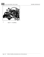
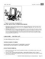
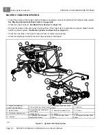
Cargo Bed – Electric Lift

BODY AND TRIM

4.

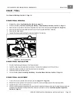
Remove the locknut, bolt, sleeve, spacers and washers from the rod end of the bed lift motor and bed frame.

5.

Remove the locknut, bolt, sleeve, spacers and washers from the base of the bed lift motor and vehicle frame
and remove the bed lift motor.

BED LIFT MOTOR INSTALLATION

NOTE:

If replacing the actuator, adjust the length of dimension between the base rod hole and the rod end hole

using the prior actuator as a guide. The rod end of the actuator can be turned clockwise to shorten and
counterclockwise to lengthen the dimension.
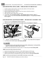
1.

With the bed in the down position, working from under the vehicle, mount the base of the bed lift motor to
the frame bracket.

1.1. Slide the metal sleeve into the bed lift motor base rod with two spacer washers on each side.

1.2. Slide a lockwasher onto the bolt and up against the bolt head.

1.3. Fit the base between the frame bracket.

1.4. Slide the bolt through the frame bracket and actuator base.

1.5. Attach a lockwasher and nylon locknut finger tight.

NOTE:

Do not tighten the lose mounting hardware until the rod end has been secured.

2.

Attach the rod end of the bed lift motor to the bed frame bracket.

2.1. Repeat steps 3.1 through 3.4 for the rod end of the bed lift motor.

2.2. Attach a lockwasher and nylon locknut and tighten to 23 ft-lb (31 N·m).

3.

Tighten the locknut on the bed lift motor base to 30 ft-lb (41 N·m).

4.

Attach the two electric wire connectors, red to red and yellow to yellow.

5.

Connect battery.

See Connecting the Battery – Gasoline/Diesel Vehicles, Section 1, Page 1-4.

CARGO BED REMOVAL

NOTE:

Cargo bed removal will be easier with the aid of an assistant.

1.

Remove the electric actuator.

See Bed Lift Motor Removal on page 4-13.
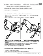
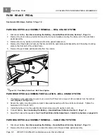
2.

With the bed in a down position, working from under the rear of the vehicle, remove the two nylon locknuts from
the cargo bed hinge and bolts.

3.

Apply slight upward pressure on the rear of the bed to relieve pressure from the hinges. Remove the hinge bolts.

4.

With the help from an additional person, or an overhead lift hoist, remove the bed from the vehicle.

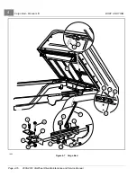
CARGO BED INSTALLATION

NOTE:

Cargo bed installation will be easier with the aid of an assistant.
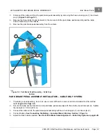
1.

With the help from an additional person, or an overhead lift hoist, place the bed onto the vehicle frame and
align the bed hinge brackets with the frame brackets.
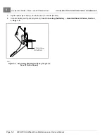
2.

Start the bolts into both hinges with the bolt heads to the outside. Use an alignment tool if necessary.

3.

Use a small hammer, and lightly tap the bolts through the hinges.

4.

Install a nylon locknut on each bolt, and tighten the hardware to 15 ft-lb (21 N·m).

Page 4-14

2008-2012 All-Wheel Drive Maintenance and Service Manual

Содержание Carryall 295 SE

Страница 1: ...2008 2012 All Wheel Drive Maintenance and Service Manual Carryall 295 295 SE XRT 1550 1550 SE and IntelliTach Gasoline and Diesel Vehicles Manual Number 103373117 Edition Code 1007F0811E...

Страница 2: ......

Страница 3: ...LLC to assist its distributors and dealers in continually updating their service knowledge and facilities so they can provide prompt and efficient service for vehicle owners Regional technical repres...

Страница 4: ...Damage to a vehicle or component thereof not resulting from a defect or that occurs due to unreasonable or unintended use overloading abuse or neglect including failure to provide reasonable or necess...

Страница 5: ...the Stored Vehicle to Service 3 8 Lifting The Vehicle 3 9 Lifting Only The Front 3 9 Lifting Only The Rear 3 9 Lifting The Entire Vehicle 3 10 Using A Booster Battery Jump Starting 3 11 SECTION 4 BODY...

Страница 6: ...Accelerator Pedal Removal From Late 2010 Model Year 5 3 Accelerator Pedal Installation From Late 2010 Model Year 5 3 Brake Pedal 5 5 Brake Pedal Removal 5 5 Brake Pedal Installation 5 5 Brake Pedal Ad...

Страница 7: ...ble Only System 6 32 Park Brake Equalizer Removal Bell Crank System 6 32 Park Brake Equalizer Installation Bell Crank System 6 32 Park Brake Equalizer Removal Cable Only System 6 33 Park Brake Equaliz...

Страница 8: ...Engine Oil and Filter Change 10 9 Oil Viscosity 10 12 Spark Plugs 10 13 Spark Plug Cleaning And Inspection 10 13 Spark Plug Gap Inspection 10 13 Gearcase Lubrication 10 13 Lubrication Level Check for...

Страница 9: ...10 Testing the Bed Lift Switch 13 10 Bed Lift Switch Removal 13 10 Bed Lift Switch Installation 13 10 Bed Lift Circuit Breaker 13 10 Testing the Bed Lift Circuit Breaker 13 10 Bed Lift Circuit Breaker...

Страница 10: ...Relay Installation 14 2 Neutral Switch 14 2 Testing the Neutral Switch 14 2 Neutral Switch Removal 14 2 Neutral Switch Installation 14 2 Fuel Solenoid 14 3 Testing the Fuel Solenoid 14 3 Fuel Solenoi...

Страница 11: ...uel Level Sending Unit 14 14 Testing the Fuel Level Sending Unit 14 14 Fuel Level Sending Unit Removal 14 15 Fuel Level Sending Unit Installation 14 15 Alternator 14 15 Testing the Alternator 14 15 Al...

Страница 12: ...oval 15 27 Air Filter Intake Hose Installation 15 28 Air Filter Outlet Hose Removal 15 29 Air Filter Outlet Hose Installation 15 29 Clutches 15 30 Clutch Troubleshooting 15 31 Drive Belt 15 31 Drive C...

Страница 13: ...9 Rear Axle Starting 2012 Model Year 17 11 Rear Axle Removal 17 11 Rear Axle Installation 17 12 Rear Driveshaft 17 13 Rear Driveshaft Removal 17 13 Rear Driveshaft Installation 17 13 Transmission 17 1...

Страница 14: ...allation 19 22 Quick Connect Fittings Auxiliary Hydraulic Circuit only 19 23 Quick Connect Removal 19 23 Quick Connect Installation 19 23 Cylinders 19 24 Vehicle Mounted Cylinders 19 24 Auxiliary Cyli...

Страница 15: ...ury or death Contact your dealer DANGER A DANGER indicates an immediate hazard that will result in severe personal injury or death The color associated with Danger is RED WARNING A WARNING indicates a...

Страница 16: ...m until the tire is completely removed Inflated tires can generate a gas mixture with the air that can be ignited by high temperatures from welding procedures performed on the wheel or rim Removing th...

Страница 17: ...electrical and mechanical repair The appropriate instructions must be used when performing maintenance service or accessory installation To avoid unintentionally starting the vehicle disconnect batte...

Страница 18: ...Gasoline Vehicles Only Connect the spark plug wire s to the spark plug s RECYCLING LEAD ACID BATTERIES WARNING Lead acid batteries contain lead Pb other metals acids and other compounds If improperly...

Страница 19: ...e safety symbols on the vehicle battery or batteries 1 2 3 4 5 6 1 Shield eyes 3 No smoking no open flames no sparks 5 Battery acid hazard 2 Read and follow operating instructions 4 Keep away from chi...

Страница 20: ......

Страница 21: ...ssion Forward and reverse with neutral 5 39 1 forward 7 79 1 reverse Electrical system 12 volt 500 cca at 0 F 17 8 C 650 at 32 F 0 C 105 minute reserve capacity and 35 amp charging capacity Torque con...

Страница 22: ...ssenger diesel with all terrain tires 1450 lb 657 6 kg 1597 lb 724 2 kg 1630 lb 739 2 kg 1734 lb 786 4 kg Forward speed 25 mph 40 km h Governed RPM 3825 Turning Radius 138 in 350 5 cm 204 in 518 2 cm...

Страница 23: ...Esso Hydraul 56 lubricant 20 oz 600 mL Transmission Mobil 424 Exxon Hydraul 560 or Esso Hydraul 56 lubricant 20 oz 600 mL Engine coolant mixture of 55 propylene glycol and 45 water n a 2 gal 7 8 L n...

Страница 24: ...over shock absorbers Rear 2012 and newer vehicles Semi independent four link suspension with coil over shock absorbers Brakes Hydraulic brake system brake pads and discs on each wheel with separate f...

Страница 25: ...2 dB A 2 070 min Sound level external per 74 151 EEC Annex VI as amended by 2006 96 EC Variant Version All Moving 79 9 dB A Stationary 73 9 dB A Engine Speed 2 700 min Vibration at driver s seat per...

Страница 26: ...with coil over shock absorbers Steering Self adjusting rack and pinion Ackerman Brakes Hydraulic brake system brake pads and discs on each wheel with separate foot operated park brake BODY CHASSIS Fra...

Страница 27: ...ing accessories 3200 lb 1451 kg Standard seating capacity 2 LIQUID CAPACITIES Engine crankcase with filter SAE 10W 30 API classification CF 3 qt 2 8 L Front differential Mobil 424 Exxon Hydraul 560 or...

Страница 28: ......

Страница 29: ...r to the owner s manual provided with the vehicle for information on the following topics Safety Decal Identification Controls and Indicators Driving Instructions Towing with the Vehicle Transporting...

Страница 30: ...rth America Vehicle 3 2 4 5 6 10 7 1 9 11 8 1 Hood 2 ROPS 3 Fuel Fill Cap 4 Cargo Bed 5 Engine Compartment Battery Fuel Tank under seat 6 Bucket Seats 7 Brake Fluid Reservoir under hood 8 Radiator and...

Страница 31: ...o identify the correct owner s manual for a vehicle This owner s manual is valid for the build code range indicated on the back cover of this owner s manual IDENTIFICATION NUMBERS Write your vehicle m...

Страница 32: ...L INFORMATION 830 Figure 3 6 Gasoline Engine Serial Number Location 831 Figure 3 7 Diesel Engine Serial Number Location 1633 Figure 3 8 Differential Serial Number Location Page 3 4 2008 2012 All Wheel...

Страница 33: ...within a given model year See following NOTE NOTE Have the vehicle serial number available when ordering parts or making inquiries Build Code The build code 4 is a five digit number that appears on th...

Страница 34: ...D IN USA 4 1 2 3 1400 Figure 3 10 Serial Number Decal with the Vehicle Build Code 2474 Figure 3 11 ROPS Serial Number Location 831 Figure 3 12 Diesel Engine Serial Number Location 1633 Figure 3 13 Dif...

Страница 35: ...key and leave the Forward Reverse handle in the NEUTRAL position during storage This is to prevent unintentionally starting the vehicle or a fire hazard Gasoline vehicles only Turn fuel shut off valv...

Страница 36: ...nk 6 1 Fill the fuel tank with fresh fuel 6 2 Disconnect the fuel vent line from the fuel tank vent nipple Figure 10 25 Page 10 17 6 3 Plug the fuel tank vent nipple so that it is air tight The manufa...

Страница 37: ...6 Perform the Pre Operation and Daily Safety Checklist See the Pre Operation and Daily Safety Checklist in the vehicle owner s manual LIFTING THE VEHICLE See General Warnings on page 1 2 LIFTING ONLY...

Страница 38: ...or rear wheels and loosen the lug nuts 4 If removing wheels loosen the lug nuts 5 Release the park brake and lift the front of the vehicle with a chain hoist or floor jack See preceding WARNING 6 Pla...

Страница 39: ...ry 3 Access the engine compartment by raising the cargo bed See WARNING For vehicles with cargo beds in General Warnings on page 1 2 4 Locate the vehicle battery on the driver s side of the vehicle un...

Страница 40: ...3 Using A Booster Battery Jump Starting GENERAL INFORMATION POS NEG P O S N E G 4 2 3 1 223 Figure 3 17 Jump Starting Page 3 12 2008 2012 All Wheel Drive Maintenance and Service Manual...

Страница 41: ...dy cleaning use automotive cleaning solutions with a sponge or soft cloth The Geloy XTW body panel material is the same material used in various automotive applications Automotive cleaning polishing p...

Страница 42: ...or equivalent Buff slowly and steadily over small area so as not to heat surface as this may cause warping or melting of plastic Buff sanded area until all sanding scratches have disappeared Use as m...

Страница 43: ...he instrument panel 11 Kawasaki Powered Gasoline vehicles Remove the choke cable from the engine choke lever See Choke Cable Removal on page 15 21 12 Remove instrument panel from vehicle INSTRUMENT PA...

Страница 44: ...nd securely prop open hood 2 Remove the four Torx screws that secure the hood to the hood hinge 3 Separate the hood and the hood hinge and remove hood from vehicle 4 Retain hardware HOOD INSTALLATION...

Страница 45: ...tabs from the fender flare 6 Lift up on the front of the side cowl panel enough to disengage the rear side tab from the slot in the front side of the instrument panel 7 Twist the front outside edge of...

Страница 46: ...t floorboard using three hex head screws Make sure that the floor mat is captured underneath the fender flare 3 Tighten the hardware at the floorboard to 55 in lb 6 2 N m 4 Reinstall front fascia See...

Страница 47: ...NOTE It may facilitate removal to use a rubber mallet to disengage the rear most tube of the side support first Finally disengage the front end of the tube by simultaniously twisting side to side and...

Страница 48: ...e value could result in damage to the ROPS tubing and stripped threads on the hardware Ensure that the ROPS is properly installed before operating the vehicle 4 Position the two rear support tubes 16...

Страница 49: ...shers and bolts and tighten the hardware to 80 in lb 9 0 N m 1 5 Install the seat See following WARNING WARNING Ensure that the seat hinges and latch are securely engaged before operating vehicle 2 Tr...

Страница 50: ...ary use a solution of mild soap and lukewarm water Do not use bleach dye or abrasive cleaners as they may severely weaken the safety belts Do not insert coins clips etc into the safety belt buckle For...

Страница 51: ...bly on the outside of the ROPS seat support with a new thread forming bolt Figure 4 2 Page 4 11 Orient the assembly with the tang end pointed up slightly and tighten the hardware to 55 ft lb 75 N m BE...

Страница 52: ...Page 4 12 Orient the assembly with the tang end pointed up slightly and tighten the new lock nut to 35 ft lb 47 5 N m SEAT BELT REMOVAL HOMOLOGATED MODELS 1 Driver seat Remove the flange bolts 1 and n...

Страница 53: ...ROPS seat support with the shoulder bolt and a new lock nut Figure 4 4 Page 4 12 Orient the assembly with the tang end pointed up slightly and tighten the new lock nut to 33 ft lb 44 7 N m CARGO BED E...

Страница 54: ...of the bed lift motor 2 2 Attach a lockwasher and nylon locknut and tighten to 23 ft lb 31 N m 3 Tighten the locknut on the bed lift motor base to 30 ft lb 41 N m 4 Attach the two electric wire connec...

Страница 55: ...e the rear edge of the bed approximately 6 inches 15 2 cm and pull the bed assembly toward the rear of the vehicle approximately 3 inches 7 6 cm to release bed latch 10 from the latch plate 11 Lift th...

Страница 56: ...4 Cargo Bed Manual Lift BODY AND TRIM 4 3 17 11 5 2 7 6 16 16 13 12 1 13 10 8 15 14 9 1884 Figure 4 7 Cargo Bed Page 4 16 2008 2012 All Wheel Drive Maintenance and Service Manual...

Страница 57: ...fender from the frame 3 Remove the two Phillips head screws and washers retaining the fender to the side of rear frame 4 Remove the fender 5 Repeat steps 1 through 4 to remove the remaining rear fende...

Страница 58: ......

Страница 59: ...the cable strain relief from the pedal bracket 4 Disconnect the Z shaped end 1 of the accelerator cable from the pedal Figure 5 1 Page 5 1 1885 Figure 5 1 Z Shaped Cable End Gasoline Vehicles 5 Remove...

Страница 60: ...ge 1 3 2 Initially adjust the ground speed set screw to 3 4 inches 19 mm as shown Figure 5 3 Page 5 2 3 4 INCH 19 MM 1886 Figure 5 2 Accelerator Pedal Assembly 1887 Figure 5 3 Ground Speed Set Screw A...

Страница 61: ...4 6 2359 Figure 5 4 Z Shaped Cable End At Accelerator Pedal 2360 Figure 5 5 Accelerator Pedal Mounting Hardware 3 Remove the pedal pivot bolt 1 and locknut 2 that secures the pedal assembly to the ch...

Страница 62: ...1 and locknut 2 to 30 ft lb 68 N m 4 Connect battery and spark plug wire s See Connecting the Battery Gasoline Diesel Vehicles Section 1 Page 1 4 2 7 16 1 8 in 61 3 mm 2361 Figure 5 6 Accelerator Peda...

Страница 63: ...n the frame brackets 2 Install the allen head shoulder bolt and locknut Tighten the hardware to 4 8 ft lb 6 5 N m 3 Install the master cylinder rod and threaded clevis pin assembly 4 Install the clevi...

Страница 64: ...em PARK BRAKE PEDAL ASSEMBLY INSTALLATION BELL CRANK SYSTEM 1 If installing a used assembly be sure to use a small stiff brush to remove all dirt and debris from the ratchet teeth Figure 5 8 Page 5 6...

Страница 65: ...EMBLY INSTALLATION CABLE ONLY SYSTEM 1 If installing a used assembly be sure to use a small stiff brush to remove all dirt and debris from the ratchet teeth Figure 5 9 Page 5 7 2 Secure the cable anch...

Страница 66: ......

Страница 67: ...from side to side to check for worn parts Excessive side movement indicates loose or worn pedal mounting parts If worn parts are found replace the worn parts then adjust the brake pedal See Brake Ped...

Страница 68: ...e vent holes in the reservoir cap and clean or replace as necessary Check the diaphragm inside the reservoir cap and replace if damaged A A 1 2 3 4 6 7 10 16 5 8 9 10 15 14 13 12 13 11 1 Brake Fluid R...

Страница 69: ...ld the vehicle stationary on an incline of 20 or less If not adjust the park brake See Front Park Brake Cable Adjustment Cable Only System on page 6 28 Check the park brake cables equalizer and linkag...

Страница 70: ...ed DOT 5 silicone brake fluid See Purging the Hydraulic System on page 6 26 Weak bulging brake hoses that expand under pressure Check the master cylinder brake lines and hoses for leaks or bulges Repl...

Страница 71: ...sion on page 7 1 Decreasing brake pedal travel Sticking caliper piston Replace the caliper See Brake Pads and Caliper 2008 2011 Models on page 6 6 Bent damaged or incorrect brake pads Replace the brak...

Страница 72: ...d in the hydraulic system Use only DOT 5 brake fluid See Bleeding the Hydraulic Brake System on page 6 24 Prior to servicing hydraulic brakes thoroughly clean the vehicle paying particular attention t...

Страница 73: ...6 24 Front Brake Caliper Installation 1 Install caliper and if equipped insert one shim washer between the caliper and upright at each mounting point Secure with two new lock patch bolts tightened to...

Страница 74: ...ARNING If at any point in this procedure the hydraulic system is opened the brakes must be bled after the correct reinstallation of the brake components Failure to bleed the brakes could result in dec...

Страница 75: ...with a new banjo bolt and new copper washers Tighten the hardware to 13 ft lb 18 N m See following NOTE and CAUTION NOTE Position the brake line so it is perpendicular to the caliper assembly and poi...

Страница 76: ...peration On a flat open surface accelerate the vehicle to moderate speed then apply the brakes under modest steady pressure Repeat this procedure for eight to twelve times 7 Adjust the parking brake S...

Страница 77: ...e on the frame so that it does not hang suspended by the hydraulic brake hose 4 Remove the outer tie rod end from the upright 5 Remove the lower ball joint from the upright Figure 6 8 Page 6 11 1897 F...

Страница 78: ...blocks 1 onto the platen bars of a hydraulic press Figure 6 10 Page 6 12 8 2 Position the disc 6 and upright 5 between the blocks 8 3 Place a 2 x 1 4 inch flat steel bar 2 under each arm of the uprigh...

Страница 79: ...on 2 x 2 inch or larger steel blocks 1 as shown Figure 6 12 Page 6 13 10 2 Position a new bearing 7 into the bearing cavity of the upright 10 3 Use a bar or rod 8 slightly smaller than the outside dia...

Страница 80: ...Upright Bearing and Shaft Assembly FRONT WHEEL DISC AND HUB INSTALLATION WARNING If at any point in this procedure the hydraulic system is opened the brakes must be bled after the correct reinstallat...

Страница 81: ...e systems See Brake System Inspection on page 6 1 REAR WHEEL DISC REMOVAL WARNING If at any point in this procedure the hydraulic system is opened the brakes must be bled after the correct reinstallat...

Страница 82: ...System on page 6 24 1 Clean the spline and threaded portion of the axle 2 Apply anti seize compound to both the axle and wheel hub splined area See following CAUTION CAUTION Do not allow anti seize c...

Страница 83: ...ulic brakes thoroughly clean the vehicle paying particular attention to areas immediately surrounding hydraulic connections to prevent dirt or debris from entering system CAUTION Do not pump the brake...

Страница 84: ...kes must be bled after the correct reinstallation of the brake components Failure to bleed the brakes could result in decreased braking performance due to air being trapped in the hydraulic system Use...

Страница 85: ...ed that respective front wheel Ensure hydraulic hoses cannot contact any moving parts that will cause wear and damage 5 Repeat procedure for the opposite brake if necessary 6 Install the tire and whee...

Страница 86: ...replace if necessary See Brake Disc and Pad Inspection on page 6 3 NOTE If brake pads are replaced on one side replace the opposite side also 3 Install the pads and caliper See Brake Pad and Caliper...

Страница 87: ...from the master cylinder FRONT BRAKE LINE INSTALLATION 1 Feed the new front brake line under the front of the vehicle and up to the master cylinder 2 Carefully insert the flared end of the brake line...

Страница 88: ...lastic bag around each caliper to prevent debris from entering the brake line ports Do not allow brake fluid to contact the brake pads and disc 6 Remove each brake line from the grommet and clamp loca...

Страница 89: ...r is accessible by opening the hood Do not allow the brake fluid level to fall below the MIN line Use only DOT 5 brake fluid MASTER CYLINDER REMOVAL WARNING To perform this procedure the hydraulic sys...

Страница 90: ...dal Adjustment Section 5 Page 5 5 7 Inspect the brake system See Brake System Inspection on page 6 1 2038 Figure 6 23 Master Cylinder Rod and Brake Pedal BLEEDING THE HYDRAULIC BRAKE SYSTEM See Genera...

Страница 91: ...ect an air hose to the vacuum brake bleeder The air pressure must be regulated at 12 to 15 psi 0 827 to 1 034 Bars 5 4 Press the handle on the brake bleeder to start the vacuum 5 5 With the vacuum run...

Страница 92: ...down the friction material 6 6 Check the master cylinder fluid level and add fluid if necessary Always pour fluid into the master cylinder slowly to avoid creating air bubbles in the reservoir See fo...

Страница 93: ...sure that the path of the vehicle is clear before the vehicle is pushed NOTE Adjust rear brake calipers and park brake before adjusting park brake cable See Park Brake Adjustment At Rear Calipers on p...

Страница 94: ...g easy and firm resistance is achieved 5 Release the park brake pedal and push it again to seven clicks The vehicle should not be movable with one person pushing 6 Tighten the jam nut against the hex...

Страница 95: ...age 6 29 Right Rear Cable Installation 1 Install the caliper end of the cable into the brake caliper arm Figure 6 24 Page 6 29 2 Slide the sheath ferrule through the hole in the caliper mounting brack...

Страница 96: ...e 2 Remove the spring from the threaded adjustment rod Figure 6 27 Page 6 31 3 Remove the nuts from the threaded adjustment rod on the cable end 4 Release the tines securing the cable ferrule to the f...

Страница 97: ...ust the brake cable equalizer See Front Park Brake Cable Adjustment Bell Crank System on page 6 27 9 Inspect all of the brake systems to ensure that both the hydraulic brake system and the park brake...

Страница 98: ...ke systems to ensure that both the hydraulic brake system and the park brake system are adjusted and operating correctly before the vehicle is returned to service See Brake System Inspection on page 6...

Страница 99: ...tment rod 4 Remove the rear park brake cables from the equalizer and remove the equalizer PARK BRAKE EQUALIZER INSTALLATION CABLE ONLY SYSTEM 1 Secure the equalizer to the ends of the rear park brake...

Страница 100: ......

Страница 101: ...ering wheel retaining bolt 4 6 Remove the steering wheel See following NOTE NOTE The steering wheel has a tapered hex fitting A steering wheel puller CC P N 102061201 may be required to remove the ste...

Страница 102: ...ge 1 2 STEERING COLUMN REMOVAL 1 Disable the vehicle See Disabling the Vehicle on page 1 3 2 Disconnect battery See Disconnecting the Battery Gasoline Diesel Vehicles Section 1 Page 1 3 3 Remove the s...

Страница 103: ...ft lb 24 N m NOTE Be sure to tighten the bolt at the universal joint on the rack and pinion shaft before tightening the steering column coupling bolt 5 Tighten the steering column coupling bolt to 18...

Страница 104: ...1 Lift and support the front of vehicle and remove the wheels See Lifting The Vehicle on page 3 9 2 Remove the outer drag link ball joints from the upright assemblies and inspect for excessive wear an...

Страница 105: ...and tighten the hardware to 21 ft lb 28 4 N m 10 Adjust the inner drag link jam nuts and tighten the hardware to 21 ft lb 28 4 N m 11 Remove the vehicle jack stands and lower the vehicle to the ground...

Страница 106: ...the snap ring 4 Figure 7 11 Page 7 6 4 16 2051 Figure 7 10 Remove Dust Seal 2052 Figure 7 11 Remove Pinion Snap Ring 9 Install the universal joint on the pinion and place a fork or a large open end w...

Страница 107: ...igure 7 16 Page 7 8 If either is excessively worn replace both ball joints 13 1 Secure the rack and housing assembly in a vise Figure 7 14 Page 7 7 See following CAUTION CAUTION Use wood blocks betwee...

Страница 108: ...ck and Pinion STEERING AND FRONT SUSPENSION 13 4 15 17 3 16 2 23 12 19 12 11 10 24 9 5 6 8 7 1 14 2057 Figure 7 16 Steering Gear Assembly Page 7 8 2008 2012 All Wheel Drive Maintenance and Service Man...

Страница 109: ...assembly into the housing The gear teeth or the small bearing could be damaged 4 Install the snap ring 4 5 Use a socket to apply pressure evenly and press in a new dust seal Figure 7 17 Page 7 9 1 2...

Страница 110: ...nd to the inner ball joint threads to minimize corrosion 17 Loosely install and advance the two nuts and drag links to the inner ball joint Figure 7 8 Page 7 5 Nuts will be tightened during the toe in...

Страница 111: ...e rear face tire measurement Proper toe in is 3 16 to 1 4 inch 4 8 to 6 35 mm 3 16 inch 4 8 mm Toe in Adjustment 1 Loosen the jam nuts on both ends of each drag link Figure 7 22 Page 7 11 2 Rotate bot...

Страница 112: ...camber for this vehicle should be from zero to 0 275 inch 7 0 mm maximum See following NOTE NOTE A good average dimension for this specification is 5 32 inch 4 mm negative camber on each wheel Camber...

Страница 113: ...ings and cause a leak in the hydraulic system diminished brake performance or brake failure 5 Remove the drag link ball joint from the upright assembly Figure 7 26 Page 7 13 2065 Figure 7 26 Drag Link...

Страница 114: ...e ball joint if it is worn loose or the rubber boot has been damaged 1 1 Remove the C clip from the top of the ball joint 1 2 Push or drive out the ball joint on the threaded shaft side See following...

Страница 115: ...and new flanged locknuts in both the front and rear frame attachments Tighten the hardware to 40 ft lb 54 N m 5 Secure the brake line bracket to the A arm and tighten the hardware to 11 ft lb 15 N m...

Страница 116: ...face of the ball joint Once the Loctite is applied slide the ball joint into the lower control arm slide adjuster Make sure the ball joint is seated up to the shoulder and wipe off any excess Loctite...

Страница 117: ...See Lifting The Vehicle on page 3 9 2 Place a floor jack under the lower A arm at the lower ball joint and raise the jack just enough to allow the A arm assembly to rest on the jack 3 Remove the flang...

Страница 118: ...e lug nuts to 87 ft lb 118 N m 7 Repeat steps 1 through 6 for the remaining shock absorber STEERING UPRIGHT INSTALLATION 1 Slide the upright and wheel hub assembly onto the splined half shaft spindle...

Страница 119: ...n the wheels with regard to which side of the vehicle they will be used on The arrow molded on the sidewall indicates designed rotation when vehicle is moving forward Figure 8 1 Page 8 1 Direction of...

Страница 120: ...ires are directional For optimum performance on muddy terrain install all four tires as shown Figure 8 1 Page 8 1 2 Lower the vehicle and use a crisscross pattern to finish tightening the lug nuts to...

Страница 121: ...lowed to seat the bead of the tire and inflate to seat tire on wheel Do not exceed pressure noted on sidewall See following DANGER DANGER Over pressurizing the tire can cause the tire to explode or co...

Страница 122: ......

Страница 123: ...gn internally 2012 Model Year and Newer The standard duty rear coil over springs and shocks are painted black Heavy duty rear coil over springs and shocks have shock housings painted black and springs...

Страница 124: ...coil spring from the previous shock absorbers as a reference See following NOTE NOTE When shock absorbers are installed ensure both shock absorbers have identical part numbers 1 Install the top bolt f...

Страница 125: ...frame SWING ARM INSTALLATION 1 Replace the urethane bushings in the swing arm brackets on the frame 2 Install new teflon impregnated steel sleeves into new swing arm urethane bushings 3 Install the u...

Страница 126: ...ent in design internally 2012 Model Year and Newer The standard duty rear coil over springs and shocks are painted black Heavy duty rear coil over springs and shocks have shock housings painted black...

Страница 127: ...ers as a reference See following NOTE NOTE When shock absorbers are installed ensure both shock absorbers have identical part numbers 1 Installation is the reverse of removal 2 Tighten the upper and l...

Страница 128: ...3 Page 3 9 3 Support the rear axle 4 Remove the hardware securing the lateral link 1 to the chassis Figure 9 6 Page 9 7 5 Remove the hardware securing the lateral link 1 to the rear axle LATERAL LINK...

Страница 129: ...REAR SUSPENSION Trailing Arms and Lateral Links Starting 2012 Model Year 9 2 1 3 2495 Figure 9 6 Rear Suspension Components 4 Link 2008 2012 All Wheel Drive Maintenance and Service Manual Page 9 7...

Страница 130: ...age 9 7 6 Remove the hardware securing the front of the trailing arm to the chassis and remove the trailing arm TRAILING ARM INSTALLATION 1 Installation is the reverse of removal Figure 9 6 Page 9 7 O...

Страница 131: ...Schedule and the Periodic Lubrication Schedule must be followed to keep the vehicle in optimum operating condition PERIODIC SERVICE SCHEDULE REGULAR INTERVAL SERVICE Pre Operation and Daily Safety Che...

Страница 132: ...er brake lines and hoses for damage or leakage Check park brake cables for damage replace if necessary Semiannual service by trained technician only or every 50 hours of operation whichever comes firs...

Страница 133: ...e Check for loose hardware and tighten if necessary Fuel filters Replace Dispose of used filters properly Safety decals Check safety decals Replace if damaged or illegible Every 200 hours of operation...

Страница 134: ...annually by owner or trained technician or every 50 hours of operation whichever comes first 2008 2011 vehicles only Rear suspension 2 fittings Chassis Lube EP NLGI Grade 2 First change 50 hours addit...

Страница 135: ...PERIODIC MAINTENANCE Periodic Lubrication Schedule 10 5 6 3 1 4 2 2 3 200 Figure 10 2 Lubrication Points Diesel Vehicles 2008 2012 All Wheel Drive Maintenance and Service Manual Page 10 5...

Страница 136: ...trained technician or every 50 hours of operation whichever comes first Attachment Arm and Interface 8 fittings Chassis Lube EP NLGI Grade 2 First change 50 hours additional change every 100 hours of...

Страница 137: ...hichever occurs first or whenever the attachment arm and interface are removed and reinstalled on the vehicle Lubricate the following locations as shown Figure 10 4 1 Attachment Interface Cylinder bot...

Страница 138: ...es a leak The brake fluid reservoir diaphragm located in the cap should not have holes or other damage BRAKE FLUID Brake fluid level should be within 1 4 inch 6 mm from the top of the reservoir Figure...

Страница 139: ...hile engine is running 2 Check oil level by fully inserting the dipstick into the tube and immediately removing it 3 If the oil level is at or below the low level mark on the dipstick gauge add oil to...

Страница 140: ...engine oil when the engine is hot or even warm Hot engine oil can cause skin burns Wear safety glasses or approved eye protection when servicing the vehicle Wear rubber gloves when handling oil drain...

Страница 141: ...re removal Position the port of the plastic container so oil will be directed into the oil pan A drip guard can be made by folding a piece of cardboard thin metal or plastic under the oil filter formi...

Страница 142: ...wires See Connecting the Battery Gasoline Diesel Vehicle on page 1 4 5 With the Forward Reverse handle in the NEUTRAL position start and run the engine for three minutes and check for leaks Observe bo...

Страница 143: ...with an OEM replacement Spark Plug Type NGK BPR2ES SPARK PLUG GAP INSPECTION 1 Measure the gap with a wire type thickness gauge 2 If the gap is incorrect carefully bend the side electrode with a suit...

Страница 144: ...Differential Lubrication Level 216 Figure 10 19 Transmission Lubrication Level Transmission Clean and install the drain plug 2 before filling the transmission with new lubricant Figure 10 19 Tighten...

Страница 145: ...o find leaks Do not use your bare hand Wear safety goggles If fluid enters skin or eyes get immediate medical attention from a physician familiar with this injury 256 Figure 10 22 Joystick 266 Figure...

Страница 146: ...at or below the LOW mark add pre mixed coolant until level reaches the FULL mark If a leak is detected have it checked by a trained technician See following WARNING WARNING Coolant reservoir and radi...

Страница 147: ...e During cold weather plugged fuel lines plugged fuel systems hard starting and other unknown failures can result from use of this fuel Biodiesel is an excellent medium for microbial growth and contam...

Страница 148: ...y and must not be left in engines longer than three months This fuel type attracts moisture and may contain higher water content than conventional diesel fuel Fuel system maintenance cleaning and fuel...

Страница 149: ...th Water Separator Style A 2327 Figure 10 27 Fuel Filter with Water Separator Style B BATTERY For periodic battery maintenance see Battery on page 13 19 gasoline vehicles or page 14 21 diesel vehicles...

Страница 150: ......

Страница 151: ...ttent ignition coil failure See the Kawasaki FH680D engine manual CC P N 103351201 Low cylinder compression See the Kawasaki FH680D engine manual CC P N 103351201 Water or dirt in the fuel system and...

Страница 152: ...lt of excess choking See owner s manual Controls and Indicators See Choke Fuel pump malfunction or failure Fuel System on page 15 8 Ignition coil failure Test Procedure 21 Ignition Spark on page 11 27...

Страница 153: ...ot backshifting properly Clutches on page 15 30 Incorrect plug Spark Plugs on page 10 13 Unsuitable fuel or incorrect rich fuel mixture Fuel System on page 15 8 Spark plug wire is damaged See the Kawa...

Страница 154: ...utral switch failure failed open Test Procedure 15 Neutral Switch Transmission on page 11 24 Starter fails to operate Transmission shifter linkage is binding or is out of adjustment Forward Reverse Sh...

Страница 155: ...dure 22 Engine Kill Wire on page 11 28 Engine won t stop running Key switch failure Test Procedure 24 Key Switch Engine Kill Circuit on page 11 29 Oil level sensor failure See the Kawasaki FH680D engi...

Страница 156: ...10 amp fuse blows repeatedly Diode 1 failed closed Test Procedure 10 Diode 1 on wire 32 and 35 on page 11 21 25 amp fuse blows repeatedly Diode 4 failed closed Test Procedure 13 Diode 4 on wire 130 a...

Страница 157: ......

Страница 158: ...SYSTEM GASOLINE VEHICLES WIRING DIAGRAM G M 6 7 1 4 2 DIODE 1 DIODE 2 DIODE 3 FRONT DIFFERENT IAL LIMITSWITCH WD1033057 7 L Figure 11 1 Wiring Diagram Gasoline Utility Vehicles Front Page 11 8 2008 20...

Страница 159: ...G AND ELECTRICAL SYSTEM GASOLINE VEHICLES Wiring Diagram 11 DIODE 5 DIODE 4 WD1033057 7 R Figure 11 2 Wiring Diagram Gasoline Utility Vehicles Rear 2008 2012 All Wheel Drive Maintenance and Service Ma...

Страница 160: ...24 Key Switch Engine Kill Circuit 25 Reverse Warning Buzzer Limit Switch If Equipped 26 Reverse Warning Buzzer If Equipped 27 Carburetor Solenoid Circuit 28 Low Oil Warning Light Circuit 29 12 Volt Ac...

Страница 161: ...ip onto the vehicle body Battery acid will cause permanent damage Wash off immediately 1 Disable the vehicle See Disabling the Vehicle on page 1 3 2 Check for loose or corroded battery terminal connec...

Страница 162: ...ge or it may be a weak cell When the variations between cells reach 0 050 or more the battery should be replaced Voltage Test 1 Disable the vehicle See Disabling the Vehicle on page 1 3 2 Check for lo...

Страница 163: ...9 6 volts at 70 F 21 C electrolyte temperature check the starter See the Kawasaki FH680D engine manual CC P N 103351201 See also the following NOTE NOTE Record the voltage reading at 70 F 21 C At low...

Страница 164: ...Repair or replace as required 4 Check the engine ground wire w203 located on the remote oil filter bracket for corrosion loose connections and or damage Figure 11 7 Page 11 15 Repair or replace as req...

Страница 165: ...ohms 5 Turn the key switch ON Place the red probe of the multimeter on the B terminal and the black probe on the L terminal of the key switch The reading should indicate continuity If the reading doe...

Страница 166: ...e the key switch See Key Switch Removal on page 13 8 TEST PROCEDURE 6 Starter Control Circuit See General Warnings Section 1 Page 1 2 1 Disable the vehicle See Disabling the Vehicle on page 1 3 2 Disc...

Страница 167: ...art relay wire w110 terminal and the frame ground Figure 11 10 Page 11 18 5 Monitor the multimeter The reading should indicate 0 volts with the key in the OFF and ON positions The reading should indic...

Страница 168: ...38 w110 and w43 See Wiring Diagram on page 11 8 TEST PROCEDURE 8 Carburetor Heater Relay See General Warnings Section 1 Page 1 2 NOTE Keep the battery connected during this test procedure The carburet...

Страница 169: ...4 If the multimeter indicates continuity while the key is in the ON position and the engine is off the contacts have failed closed Replace the relay 7 If the reading obtained in step 5 is not 12 VDC...

Страница 170: ...0 m 500 20k 200k 2000 k 1000 OFF WAVETEK 5XL V V V A COM 200nA MAX 1000 750V FUSED 1 4 5 A B 6 2 1 2 2 1 2 3 1 1 VOM Black Lead 2 VOM Red Lead 3 Wiring Diagram Symbol with Diode Stripe Orientation 4 G...

Страница 171: ...ure of the start relay contacts Diode 5 w131 and w129 Starter solenoid coil flyback diode Closed The 25 amp fuse on w125 will blow repeatedly when key is in START position until the diode has been rep...

Страница 172: ...arness Diode Removal on page 13 18 8 Reverse the multimeter probes and note the reading The multimeter should indicate approximately 540 mV however a range of 400 700 mV is acceptable 9 If the reading...

Страница 173: ...shows continuity with the meter probes connected as described the diode has failed and must be replaced See Wire Harness Diode Removal on page 13 18 8 Reverse the multimeter probes and note the readin...

Страница 174: ...ure 11 16 Page 11 24 3 Check for continuity on the switch contacts with the Forward Reverse handle in the FORWARD position Figure 11 17 Page 11 24 The multimeter should indicate no continuity 2090 Fig...

Страница 175: ...e wire Place the black probe on the other terminal end of the wire The reading should indicate continuity If the reading is incorrect repair or replace the wire See following NOTE NOTE When checking c...

Страница 176: ...ct battery and spark plug wire s See Disconnecting the Battery Gasoline Diesel Vehicles on page 1 3 2 Disconnect the two pin connector between the wire harness and the front drive gearcase located und...

Страница 177: ...r than 14 0 volts but rising steadily check the battery condition See Test Procedure 1 Battery on page 11 10 7 If the reading is less than 14 0 volts and not rising check the charge coil See Test Proc...

Страница 178: ...probe of the multimeter to the white black wire terminal of the six wire connector and connect the black probe to the vehicle frame ground The multimeter should indicate continuity with the key switch...

Страница 179: ...ed probe on the M terminal and the black probe on the G terminal With the key switch OFF the reading should indicate continuity With the key switch turned ON the reading should indicate no continuity...

Страница 180: ...operly wired replace the buzzer See Reverse Warning Buzzer Removal on page 13 12 TEST PROCEDURE 27 Carburetor Solenoid Circuit See General Warnings Section 1 Page 1 2 NOTE Keep the battery connected w...

Страница 181: ...let connector and the engine ground Figure 11 26 Page 11 31 The resistance should be approximately 30 ohms 2 4 If the resistance reading is incorrect replace the solenoid coil See the Kawasaki FH680D...

Страница 182: ...URE 29 12 Volt Accessory Receptacle See General Warnings Section 1 Page 1 2 NOTE Keep the battery connected during this test procedure 1 Disable the vehicle See Disabling the Vehicle on page 1 3 2 Set...

Страница 183: ...isted in the preceding table the fuel level sending unit is working properly If the readings are incorrect the fuel level sending unit has failed and the fuel tank must be replaced See Fuel Tank Remov...

Страница 184: ...11 34 6 Turn the key switch ON The voltage reading should be the same as the battery voltage reading recorded earlier If not check the continuity of the blue and black wires Figure 11 29 Page 11 34 7...

Страница 185: ...t on page 11 31 NOTE The hour meter is designed to record actual engine running time and will not start adding increments until the engine is running and the oil pressure switch has opened 5 If the ho...

Страница 186: ...Fuse on page 11 13 If the wires and fuse show continuity and the readings are still incorrect replace the switch See Light Switch Removal on page 13 11 TEST PROCEDURE 34 Voltage at Headlight Socket S...

Страница 187: ...ue wire terminal w01 of the wire harness If the multimeter reading is approximately 12 volts the blue wire has continuity 7 Check the continuity of the 16 gauge black wire w13 from the headlight to th...

Страница 188: ...are wired incorrectly Check the wiring of the bed lift harness and bed lift switch See Wiring Diagram on page 11 8 A reading of approximately 0 VDC indicates a failed bed lift switch failed bed lift c...

Страница 189: ...w7 5 14 Red w7 6 14 Yellow w5 8 14 Black w2 2104 Figure 11 36 Bed Lift Switch Terminals BED LIFT SWITCH CONTINUITY Between Terminals 1 2 4 5 6 8 1 Cont when pushed DOWN 2 Cont when pushed DOWN Cont wh...

Страница 190: ......

Страница 191: ...neral Warnings Section 1 Page 1 2 TROUBLESHOOTING GUIDE The following troubleshooting guide will be helpful in identifying operating difficulties should they occur The guide includes the symptom proba...

Страница 192: ...103840201 Fuel pump failure See the Kubota D722 diesel engine manual CC P N 103840201 Fuel leak caused by loose injection pipe retaining nut Tighten nut See the Kubota D722 diesel engine manual CC P N...

Страница 193: ...es on page 12 26 Incorrect nozzle opening pressure Injection nozzle clogged Failed injection pump Fuel overflow pipe clogged Fuel leak caused by loose injection pipe retaining nut See the Kubota D722...

Страница 194: ...ngine oil Drain engine oil and refill with specified engine oil See owner s manual Oil level is low Add engine oil See owner s manual Failed radiator fan or radiator fan circuit Test Procedure 11 Fan...

Страница 195: ...rade fuel Drain fuel and refill with specified fuel See owner s manual Fuel filter clogged Replace fuel filter See Fuel Filter Replacement on page 16 9 Black or dark gray exhaust gas is observed Air c...

Страница 196: ...2 12 Battery discharged 60 amp fusible link failed Test Procedure 22 60 Amp Fusible Link on page 12 33 Hour meter adds increments with key switch ON and engine not running Oil pressure switch failed o...

Страница 197: ......

Страница 198: ...8_BLU W41 1 2 3 4 5 6 FUEL GAUGE HOUR METER Intellitac h Diesel Veh icles Only Through mid 2009 FUEL GAUGE HOUR METER All Non Intellitach Dies el Vehicles and Only Late 20 09 Intellitach Vehicles See...

Страница 199: ...G AND ELECTRICAL SYSTEM DIESEL VEHICLES Wiring Diagram 12 DIODE 3 DIODE 4 WD1032775B7 R Figure 12 2 Wiring Diagram for Diesel Utility Vehicles Rear 2008 2012 All Wheel Drive Maintenance and Service Ma...

Страница 200: ...iagram TROUBLESHOOTING AND ELECTRICAL SYSTEM DIESEL VEHICLES WD1033181B3 Figure 12 3 Main Light Wiring Diagram Carryall 295 Homologated Vehicle Page 12 10 2008 2012 All Wheel Drive Maintenance and Ser...

Страница 201: ...NESS PROV IDING P O W ER T O LOW BE AM HEA D LIGHTS CONNE CTS TO W39 IN MA I N LIG HT HA RNE SS PICKS UP B CONNE CTS TO GND SPADE ON HO RN CONNE CTS T O W 21 IN VEHICL E HARNE S S PICK UP B PO WER CON...

Страница 202: ...60 Amp Fusible Link 23 Coolant Temperature Warning Light Circuit 24 Glow Plug Circuit 25 Reverse Warning Buzzer Limit Switch If Equipped 26 Reverse Warning Buzzer If Equipped 27 Fuel Solenoid Pull Co...

Страница 203: ...nd 1 280 at 80 F 27 C Never add acid to the battery to obtain a higher specific gravity Figure 12 5 Page 12 14 See following CAUTION CAUTION Do not allow battery acid from battery caps or hydrometer t...

Страница 204: ...e or it may be a weak cell When the variations between cells reach 0 050 or more the battery should be replaced Voltage Test 1 Disable the vehicle See Disabling the Vehicle on page 1 3 2 Check for loo...

Страница 205: ...ing exceeds 9 6 volts at 70 F 21 C electrolyte temperature check the starter See the Kubota D722 diesel engine manual CC P N 103840201 See also the following NOTE NOTE Record the voltage reading at 70...

Страница 206: ...ion damaged terminals and an excess of paint on the engine block under the starter where the two 6 gauge black wires w202 and w203 are connected Figure 12 9 Page 12 17 Repair or replace as required 5...

Страница 207: ...or clips to connect the multimeter probes between the B and A terminals With the key switch in the START position the multimeter should indicate continuity Figure 12 10 Page 12 17 If the multimeter do...

Страница 208: ...move the key switch See Key Switch Removal on page 14 7 4 Set the multimeter to 200 ohms 5 Check the B and I terminals 5 1 Use alligator clips to connect the multimeter probes between the B and I term...

Страница 209: ...hould indicate approximately 12 VDC when the key is in the START position 2109 Figure 12 11 Solenoid Coil Wire w127 Removed 2110 Figure 12 12 Starter Circuit Test 6 If the readings differ from those d...

Страница 210: ...position and the relay should click See following NOTE NOTE The fan and accessory relays may be removed to isolate the sound of the start relay click 6 If the reading is 12 VDC and the relay does not...

Страница 211: ...icate 0 volts with the key in the OFF position If not check for a short or incorrect wiring between the yellow fan relay wire w146 terminal and the key switch 3 3 The reading should indicate approxima...

Страница 212: ...F to 226 F 102 C to 108 C 185 F 85 C The fan relay activates the radiator fan when the engine coolant reaches a temperature range of 187 F to 198 F 86 C to 92 C and closes the fan thermostat switch T...

Страница 213: ...t switch 6 1 Place the thermostat switch in a kitchen pot as shown Figure 12 18 Page 12 24 6 2 Set a multimeter to 200 ohms 6 3 Use an alligator clip to connect the black probe to the thermostat switc...

Страница 214: ...ge yellow black wire in the connector 3 With the Forward Reverse handle still in the NEUTRAL position turn the key switch to the ON position The fan motor should run If not test voltage to fan motor V...

Страница 215: ...e key switch in the OFF position check the fan relay for proper wiring and function See Test Procedure 9 Fan Relay on page 12 21 12 If the voltage reading is not approximately 12 VDC with the key swit...

Страница 216: ...20k 200k 2000 k 1000 OFF WAVETEK 5XL V V V A COM 200nA MAX 1000 750V FUSED 1 4 5 A B 6 2 1 2 2 1 2 3 1 1 VOM Black Lead 2 VOM Red Lead 3 Wiring Diagram Symbol with Diode Stripe Orientation 4 Good Dio...

Страница 217: ...timeter to the diode test function 4 Connect the black probe of the multimeter to the frame ground 5 Connect the red probe of the multimeter to the 18 gauge gray wire w35 on the two pin connector wire...

Страница 218: ...ire Harness Diode Removal on page 14 20 TEST PROCEDURE 15 Diode 3 on wire 123 See General Warnings Section 1 Page 1 2 1 Disconnect battery See Disconnecting the Battery Gasoline Diesel Vehicles Sectio...

Страница 219: ...Removal on page 14 20 TEST PROCEDURE 16 Diode 4 on wire 129 See General Warnings Section 1 Page 1 2 1 Disconnect battery See Disconnecting the Battery Gasoline Diesel Vehicles Section 1 Page 1 3 2 Di...

Страница 220: ...se handle in the FORWARD position Figure 12 25 Page 12 30 The multimeter should indicate no continuity 4 Check for continuity on the switch contacts with the Forward Reverse handle in the NEUTRAL posi...

Страница 221: ...nuity If the reading is incorrect repair or replace the wire See following NOTE NOTE When checking continuity of wires in the wire harness observe the polarity of diodes Testing continuity of certain...

Страница 222: ...ntinuity when the switch lever is activated If either reading is incorrect replace the switch See Front Differential Limit Switch Removal on page 14 13 TEST PROCEDURE 20 Front Drive Gearcase Coil See...

Страница 223: ...12 12 7 If the reading is less than 14 2 volts and not rising or higher than 14 8 volts replace the alternator TEST PROCEDURE 22 60 Amp Fusible Link See General Warnings Section 1 Page 1 2 NOTE Keep...

Страница 224: ...1 3 2 At driver side raise the seat and disconnect the two pin connector from the thermostat switch Figure 12 20 Page 12 25 G N I N R A W Y R U J N I E R E V E S E S U A C N A C T O H d l o f i n a M...

Страница 225: ...See General Warnings Section 1 Page 1 2 NOTE Keep the battery connected during this test procedure 1 Disable the vehicle See Disabling the Vehicle on page 1 3 2 Set a multimeter to 20 VDC 3 Place the...

Страница 226: ...e terminal and the black probe on the other terminal of the limit switch With the limit switch lever fully released the reading should be no continuity 5 Place the Forward Reverse handle in the REVERS...

Страница 227: ...12 12 Key switch See Test Procedure 4 Key Switch Starter Circuit on page 12 17 Starter solenoid See the Kubota D722 diesel engine manual CC P N 103840201 Wire continuity of w135 See Test Procedure 18...

Страница 228: ...itch to the ON position The low oil warning light should illuminate 9 If the low oil warning light does not illuminate when the key switch is in the ON position check the 18 gauge purple wire w42 for...

Страница 229: ...float is at the surface of the fuel in the tank FLOAT POSITION RESISTANCE READING FUEL GAUGE READINGS Lower position tank empty 240 20 ohms Empty Center position tank half full 120 20 ohms Half full U...

Страница 230: ...12 36 Page 12 40 6 Turn the key switch ON The voltage reading should be the same as the battery voltage reading recorded earlier If not check the continuity of the blue and black wires Figure 12 36 P...

Страница 231: ...PROCEDURE 34 Light Switch See General Warnings Section 1 Page 1 2 NOTE The headlight circuit is protected by the 20 amp fuse Check the fuse before this procedure is performed See Test Procedure 2 Fus...

Страница 232: ...the multimeter indicates approximately 12 volts replace the headlight bulb 6 If there is no voltage reading at the wire harness check the continuity of the 16 gauge blue wire w01 and w03 from the hea...

Страница 233: ...are wired incorrectly Check the wiring of the bed lift harness and bed lift switch See Wiring Diagram on page 12 8 A reading of approximately 0 VDC indicates a failed bed lift switch failed bed lift c...

Страница 234: ...d Lift Switch Removal on page 14 9 2 Check continuity between the terminals Figure 12 43 Page 12 44 of the switch and compare the readings with the Bed Lift Switch Continuity Table If continuity readi...

Страница 235: ...pushed DOWN Cont when pushed UP 8 Cont when pushed UP TEST PROCEDURE 38 Bed Lift Circuit Breaker 1 Remove the bed lift circuit breaker See Bed Lift Circuit Breaker Removal on page 14 9 2 Place the red...

Страница 236: ......

Страница 237: ...anual CC P N 103351201 RELAYS See General Warnings Section 1 Page 1 2 The start relay 1 carburetor heater relay 2 and accessory relay optional not shown are housed on the electrical component mounting...

Страница 238: ...The neutral switch 1 is located on the transmission housing Figure 13 2 Page 13 1 TESTING THE NEUTRAL SWITCH See Test Procedure 15 Neutral Switch Transmission on page 11 24 NEUTRAL SWITCH REMOVAL 1 D...

Страница 239: ...connect the two pin connector from the carburetor solenoid Figure 13 3 Page 13 3 4 Remove the solenoid from the carburetor See the Kawasaki FH680D engine manual CC P N 103351201 2128 Figure 13 3 Carbu...

Страница 240: ...r from the engine 3 Disconnect the green wire from the carburetor heater 1 Figure 13 4 Page 13 4 4 Remove the heater from the carburetor 2129 Figure 13 4 Carburetor Heater CARBURETOR HEATER INSTALLATI...

Страница 241: ...the voltage regulator VOLTAGE REGULATOR INSTALLATION 1 Position the voltage regulator on the mounting plate and install the mounting screw Tighten screw to 30 in lb 3 4 N m Figure 13 5 Page 13 5 2 Con...

Страница 242: ...the wires from the warning light 1 Figure 13 6 Page 13 7 4 Press the retaining tabs and remove the warning light from the instrument panel WARNING LIGHT INSTALLATION 1 Push a new warning light into t...

Страница 243: ...l before indicating the actual fuel level The hour meter displays the number of hours of use in increments of 0 1 one tenth hour but does not record additional time unless the key switch is in the ON...

Страница 244: ...ircuit on page 11 15 Also see Test Procedure 24 Key Switch Engine Kill Circuit on page 11 29 KEY SWITCH REMOVAL 1 Disconnect battery and spark plug wire s See Disconnecting the Battery Gasoline Diesel...

Страница 245: ...the accessory receptacle See following NOTE NOTE The retainer works like a nut but can be removed quickly by turning only enough to align the two small patches of retainer threads with the two smooth...

Страница 246: ...and switch and reconnect the wire harness 2 Push the bed lift switch into the instrument panel until fully seated 3 Lower and secure the hood 4 Connect battery and spark plug wire s See Connecting the...

Страница 247: ...ower retaining tabs and push the light switch 11 out of the instrument panel Figure 13 6 Page 13 7 4 Disconnect the wire harness from the light switch LIGHT SWITCH INSTALLATION 1 Match the terminal nu...

Страница 248: ...ting is used damage to the vehicle electrical system may occur 2 Install the electrical component cover 3 Connect battery and spark plug wire s See Connecting the Battery Gasoline Diesel Vehicles Sect...

Страница 249: ...ing the Battery Gasoline Diesel Vehicles Section 1 Page 1 4 REVERSE WARNING BUZZER LIMIT SWITCH IF EQUIPPED See General Warnings Section 1 Page 1 2 TESTING THE REVERSE WARNING BUZZER LIMIT SWITCH See...

Страница 250: ...shown Figure 13 9 Page 13 14 5 Hold the limit switch in position and tighten the mounting screws and nuts to 4 in lb 0 5 N m See following CAUTION CAUTION Do not overtighten the retaining nuts If the...

Страница 251: ...ifferential Limit Switch Removal Through Early 2010 Model Year 2496 Figure 13 11 Front Differential Limit Switch Removal From Late 2010 Model Year FRONT DIFFERENTIAL LIMIT SWITCH INSTALLATION 1 Instal...

Страница 252: ...or to replacement TESTING THE IGNITION COIL See Test Procedure 21 Ignition Spark on page 11 27 See also Test Procedure 22 Engine Kill Wire on page 11 28 Test Procedure 23 Grounded Kill Wire on page 11...

Страница 253: ...ULB REMOVAL 1 Disconnect battery and spark plug wire s See Disconnecting the Battery Gasoline Diesel Vehicles on page 1 3 2 From the front of the vehicle reach under the cowl and turn the connector ha...

Страница 254: ...s indicated by the silver stripe on one end of the diode and mark the wire on the side of the silver stripe 4 Cut the wires attached to each side of the diode and discard the diode WIRE HARNESS DIODE...

Страница 255: ...facturer recommends a group 70 side post battery CC P N 103496801 with a 650 cranking amp rating at 32 F 0 C 500 CCA at 0 F 17 8 C and a reserve capacity of at least 105 minutes The group 70 classific...

Страница 256: ...anently inactive Check the water level more frequently in hot weather and when the battery becomes old See Figure 11 4 Page 11 12 VIBRATION DAMAGE The battery hold down clamp should always be tight en...

Страница 257: ...e battery may be charged with a slow charge 3 10 amps or a fast charge 20 30 amps Charge until the specific gravity reaches 1 250 See following WARNING WARNING If the battery case feels hot approximat...

Страница 258: ...recharged See following WARNING WARNING If the battery is frozen or the container is bulged discard battery A frozen battery can explode 6 The frequency of recharging required depends on the temperat...

Страница 259: ...e manual CC P N 103840201 RELAYS See General Warnings Section 1 Page 1 2 The start relay 1 differential relay 2 fan relay 3 and accessory relay optional not shown are housed on the electrical componen...

Страница 260: ...neutral switch 1 is located on the transmission housing Figure 14 2 Page 14 1 TESTING THE NEUTRAL SWITCH See Test Procedure 17 Neutral Switch Transmission on page 12 30 NEUTRAL SWITCH REMOVAL 1 Disabl...

Страница 261: ...ts securing the wire lead bracket and the two bolts securing the fuel solenoid to the engine Pull the solenoid and o ring from the engine Figure 14 4 Page 14 3 1 2 3 1 Bracket 2 Fuel Solenoid 3 O ring...

Страница 262: ...ehicles Section 1 Page 1 3 2 Move the terminal cover 2 and remove the nut 3 that secures the fusible link wire assembly 1 to the alternator Figure 14 5 Page 14 4 2 1 3 2138 Figure 14 5 60 Amp Fusible...

Страница 263: ...MOVAL 1 Disconnect battery See Disconnecting the Battery Gasoline Diesel Vehicles Section 1 Page 1 3 2 Raise the hood 3 Disconnect the wires from the warning light 1 Figure 14 6 Page 14 6 4 Press the...

Страница 264: ...e key switch in the OFF position the fuel gauge field is blank however the hour meter field is always ON When the key switch is turned to ON the fuel gauge field activates The fuel gauge initially reg...

Страница 265: ...d secure the hood 6 Connect battery See Connecting the Battery Gasoline Diesel Vehicles Section 1 Page 1 4 KEY SWITCH See General Warnings Section 1 Page 1 2 TESTING THE KEY SWITCH See Test Procedure...

Страница 266: ...hood disconnect the wires from the accessory receptacle 12 Figure 14 6 Page 14 6 5 Reach under the instrument panel to remove the retainer 13 securing the accessory receptacle See following NOTE NOTE...

Страница 267: ...sh the bed lift switch into the instrument panel until fully seated 3 Lower and secure the hood 4 Connect battery See Connecting the Battery Gasoline Diesel Vehicles Section 1 Page 1 4 BED LIFT CIRCUI...

Страница 268: ...IGHT SWITCH INSTALLATION 1 Match the terminal numbers molded onto the connector and switch and reconnect the wire harness 2 Push the light switch into the instrument panel until fully seated 3 Lower a...

Страница 269: ...Connecting the Battery Gasoline Diesel Vehicles Section 1 Page 1 4 REVERSE WARNING BUZZER IF EQUIPPED See General Warnings Section 1 Page 1 2 TESTING THE REVERSE WARNING BUZZER See Test Procedure 26...

Страница 270: ...WARNING BUZZER LIMIT SWITCH See Test Procedure 25 Reverse Warning Buzzer Limit Switch If Equipped on page 12 36 REVERSE WARNING BUZZER LIMIT SWITCH REMOVAL 1 Disconnect battery See Disconnecting the B...

Страница 271: ...eing properly activated 7 Connect the 18 gauge red and 18 gauge red white wires to the limit switch 8 Lower and secure the hood 9 Connect battery See Connecting the Battery Gasoline Diesel Vehicles Se...

Страница 272: ...See following CAUTION CAUTION Do not overtighten the retaining nuts If the nuts are overtightened the switch could become damaged 2 Move the accelerator pedal back and forth to ensure that the switch...

Страница 273: ...connect the 18 gauge purple wire from the alternator Figure 14 12 Page 14 15 3 Disconnect the 12 gauge blue fusible link from the alternator Figure 14 12 Page 14 15 Figure 14 13 Page 14 15 1 2 3 1 Pur...

Страница 274: ...en the belt tension is adjusted 3 Place the V belt on the alternator pulley 4 Place a belt tension gauge on the V belt and use a pry bar to increase the belt tension Use a Krikit brand belt tension ga...

Страница 275: ...LB REMOVAL 1 Disconnect battery See Disconnecting the Battery Gasoline Diesel Vehicles Section 1 Page 1 3 2 From the front of the vehicle reach under the cowl and turn the connector harness halogen bu...

Страница 276: ...est Procedure 10 Thermostat Switch on page 12 22 THERMOSTAT SWITCH REMOVAL 1 Disable the vehicle See Disabling the Vehicle on page 1 3 2 Disconnect the two pin connector between the thermostat switch...

Страница 277: ...evel in the reservoir If the coolant level is at or below the LOW mark add pre mixed coolant until the level reaches the FULL mark See Engine Coolant Diesel Vehicles Section 10 Page 10 16 5 Connect ba...

Страница 278: ...HARNESS DIODES See General Warnings Section 1 Page 1 2 The wire harness is equipped with several in line diodes TESTING THE WIRE HARNESS DIODES See Test Procedure 12 Wire Harness Diodes on page 12 26...

Страница 279: ...es away from the vehicle and service area Ventilate when charging or using in an enclosed space Wear a full face shield and rubber gloves when working on or near batteries For added protection cover t...

Страница 280: ...discharge the battery should always be kept clean Hot weather also has an effect on a battery s self discharge rate The higher the temperature the quicker a battery will discharge Therefore the batte...

Страница 281: ...personal injury when accidentally coming in contact with the skin or eyes and could damage clothing CHARGING THE BATTERY See General Warnings on page 1 2 1 Charge the battery with an automotive type 1...

Страница 282: ...y stored at 0 F 17 8 C will discharge very little over a four month period A battery stored at 80 F 27 C will have to be recharged every few weeks 5 Check the state of charge periodically A battery th...

Страница 283: ...ELECTRICAL COMPONENTS DIESEL VEHICLES Battery 14 WARNING Do not jump start a dead battery with another battery and jumper cables 2008 2012 All Wheel Drive Maintenance and Service Manual Page 14 25...

Страница 284: ......

Страница 285: ...el Vehicles on page 1 3 2 Remove the cargo bed See Cargo Bed Removal Section 4 Page 4 14 3 Remove seat s and remove the center seat plate bucket seat vehicles only 4 Remove the ROPS Roll Over Protecti...

Страница 286: ...ne Engine GASOLINE ENGINE MUFFLER FUEL SYSTEM AND CLUTCHES 9 10 11 7 6 8 4 5 1 2 3 2149 Figure 15 1 Engine Removal and Installation Components Page 15 2 2008 2012 All Wheel Drive Maintenance and Servi...

Страница 287: ...il inlet and outlet hoses from the engine See Oil Filter Hose Removal on page 15 5 See also following NOTE NOTE Plug each line as it is removed from the engine Without plugs oil will leak from the lin...

Страница 288: ...Drive Clutch Installation Both Designs on page 15 38 Also see Driven Clutch Installation on page 15 40 10 Install the drive belt See Drive Belt Installation on page 15 31 11 Install the clutch outer c...

Страница 289: ...ilter Hose Removal 1 Drain the engine oil See Engine Oil on page 10 8 2 Place a pan under the oil filter hose connections on the engine See following NOTE NOTE It s best to disconnect the engine hoses...

Страница 290: ...ft the end of the muffler inlet and intermediate pipe from side to side to relax and disconnect the springs 4 Remove the two bolts and large flat washers that secure the muffler to the chassis and rem...

Страница 291: ...ce springs that show signs of brittleness broken coils or loss of tension 1 Loosely secure the muffler and spring suspension bracket to the chassis with two bolts and large flat washers Figure 15 4 Pa...

Страница 292: ...LINES See General Warnings Section 1 Page 1 2 The fuel lines must be properly routed and all hose clamps must be tight Figure 15 5 Page 15 8 and Figure 15 6 Page 15 9 The fuel lines should be kept cl...

Страница 293: ...mp 24 3 inches 61 5 cm 3 3 16 in 5 mm Molded Vent Tube Fuel Tank to Canister 7 44 5 inches 113 cm 4 3 16 in 5 mm Vent Tube Canister 7 to Air Filter Canister 8 13 inches 33 cm 5 5 16 in 8 mm Vent Tube...

Страница 294: ...re in proper operating condition Check the following items Spark plug and gap condition See the Kawasaki FH680D engine manual CC P N 103351201 Air filter element See Air Filter Replacement on page 15...

Страница 295: ...11 After the proper jet size is determined replace the main jet See the Kawasaki FH680D engine manual CC P N 103351201 No adjustment of the pilot air screw is recommended The following chart lists th...

Страница 296: ...ead plastic thread screw 10 securing the black ground wire 6 to the fuel level sending unit and remove the black ground wire Retain the hardware 5 Remove the four remaining hex head plastic thread scr...

Страница 297: ...t are aligned properly with the mounting holes on the fuel tank 2 Feed a new sending unit rheostat arm and float 4 into the fuel tank Figure 15 8 Page 15 12 The rheostat arm and float should be positi...

Страница 298: ...tighten the hardware to 9 in lb 1 N m If the hardware cannot be tightened to 9 in lb 1 N m the fuel tank must be replaced See following CAUTION CAUTION Do not overtighten the screws Overtightening th...

Страница 299: ...pump and fuel lines is used and the engine stalls 8 Loosen the clamp and disconnect the fuel line from the fuel tank shut off valve Figure 15 11 Page 15 15 219 Figure 15 11 Gasoline Fuel Tank 9 Loosen...

Страница 300: ...hicle 2 Insert the tab end of the strap into the frame bracket and place the strap in the indentions on the tank 3 Feed the threaded tab end down into the bottom of the frame Install a nylon locknut a...

Страница 301: ...ne connection for leaks 17 1 Check all clamps at the carburetor fuel filters fuel pump and fuel tank for leaks 17 2 Inspect each fuel line to ensure that the lines are not cracked cut or worn CARBON C...

Страница 302: ...ee General Warnings Section 1 Page 1 2 The fuel shut off valve is located on top of the fuel tank The fuel shut off valve should always be turned to the closed OFF position during vehicle storage towi...

Страница 303: ...speed RPM must be adjusted See High Speed RPM Adjustment on page 15 25 1 Disconnect battery and spark plug wire s See Disconnecting the Battery Gasoline Diesel Vehicles on page 1 3 2 Raise the hood 3...

Страница 304: ...partment See following NOTE NOTE Tie a nylon cord to each end of the cable before removing it from the vehicle When removing the cable allow the cord to travel from the attachment points and under the...

Страница 305: ...2161 Figure 15 18 Z Shaped Cable End in Hole at Pedal CHOKE CABLE Choke Cable Removal 1 Disconnect battery and spark plug wire s See Disconnecting the Battery Gasoline Diesel Vehicles on page 1 3 2 R...

Страница 306: ...nto the engine front cover 4 until it snaps into place 7 Insert and secure the Z shaped end of the choke cable 2 to the choke lever on the side of the carburetor 8 Secure the choke cable return spring...

Страница 307: ...rs of use Other possible symptoms include difficulty or inability to shift into or out of gear and engine stalling 1 Operate the vehicle as usual through the break in period If this condition persists...

Страница 308: ...ned idle screw 2 out until it no longer touches the bellcrank Figure 15 24 Page 15 25 3 Hold the carburetor throttle lever 5 Figure 15 23 Page 15 25 against the carburetor idle screw 1 by pushing the...

Страница 309: ...engine produces carbon monoxide which is an odorless deadly poison 1 With engine at operating temperature press the accelerator pedal all the way to the floor 2 Measure the engine RPM with a tachomete...

Страница 310: ...heed this caution could damage the engine by allowing excessive contamination to enter the air intake system Air Filter Removal 1 Release both canister tab locks Figure 15 25 Page 15 26 2 Pull the ca...

Страница 311: ...bracket and vehicle frame bracket Tighten the hardware to 21 ft lb 28 5 N m 3 Secure the bottom inlet hose to the canister port 4 Secure the top outlet hose to the canister port 5 Install a new air fi...

Страница 312: ...racket AIR FILTER INTAKE HOSE INSTALLATION 1 Slide the air intake hose through the frame support bracket Figure 15 27 Page 15 28 2 Secure the air intake hose to the air port under the vehicle body Fig...

Страница 313: ...m the air filter canister outlet port 3 Remove the hose end from the carburetor inlet port and remove the hose AIR FILTER OUTLET HOSE INSTALLATION 1 Connect the air filter outlet hose to the air filte...

Страница 314: ...1 2 1 Spider removal tool CC P N 102607501 2 Fixed sheave tool CC P N 102601501 CC P N 103865301 2497 Figure 15 30 Drive Clutch Service Tools Two Weight Design 2498 Figure 15 31 Drive Clutch Service T...

Страница 315: ...lean all parts in the drive and driven clutches 5 Check the drive clutch rollers and weights for wear See Drive Clutch Cleaning and Inspection on page 15 32 DRIVE BELT See General Warnings Section 1 P...

Страница 316: ...a three weight drive clutch Be very careful with the clutches A clutch that has been dropped will not be properly balanced If either clutch is dropped assume that it is damaged and replace it Drive C...

Страница 317: ...1 Use a 7 16 inch socket to remove the four bolts 1 and washers 2 that secure the plate 3 to the clutch cover 4 Figure 15 35 Page 15 34 2 Remove the cover 4 and spring 5 from the clutch spider 6 3 In...

Страница 318: ...GASOLINE ENGINE MUFFLER FUEL SYSTEM AND CLUTCHES 2 3 4 5 6 10 13 12 13 12 15 14 11 7 8 9 1 2173 Figure 15 35 Drive Clutch Components Two Weight Page 15 34 2008 2012 All Wheel Drive Maintenance and Ser...

Страница 319: ...the drive clutch service tool CC P N 103865301 into a vice or mount the tool to a flat work surface 5 Place the drive clutch onto the service tool and secure the fixed sheave 15 as shown Figure 15 36...

Страница 320: ...te 7 Pin 375x1 375 12 Moveable Sheave 3 Spring Compression 2 0 OD Black Or 8 Washer Flat 13 Locknut 10 24 4 Spacer Clutch 1 44x1 125x 15 9 Button Torque Primary 14 Screw Shoulder Hex Socket 25x2 5 5 S...

Страница 321: ...ed with an X to assist in correct reassembly It is important to note the location of the X on the components and be sure to align the X s when assembling the drive clutch 1 Place the moveable sheave 1...

Страница 322: ...for the two weight drive clutch but not the clutch as a whole If the entire drive clutch is to be replaced only the three weight design will be available It will be part of a kit that includes a match...

Страница 323: ...pring compression base CC P N 102603501 1 Figure 15 38 Page 15 39 2 Place the Spring compression collar CC P N 102605201 2 onto the driven clutch 3 Thread the Spring compression nut CC P N 102606101 3...

Страница 324: ...compression collar onto the cup Figure 15 38 Page 15 39 5 Tighten the spring compression nut just enough to enable the snap ring to be installed 6 Use snap ring pliers to install the snap ring Driven...

Страница 325: ...ction 1 Page 1 4 See following NOTE NOTE Ensure the hose clamp is tightly installed and positioned between the filter canister and canister port bead Clutch Inner Cover Removal 1 Disconnect battery an...

Страница 326: ...drive belt See Drive Belt Installation on page 15 31 9 Install the clutch outer cover See Clutch Outer Cover Installation on page 15 41 10 Connect battery and spark plug wire s See Connecting the Bat...

Страница 327: ...seat frame assembly See ROPS Removal Section 4 Page 4 6 6 Drain the engine and radiator coolant system See Engine Coolant Change Section 18 Page 18 1 7 Release the clamps securing the upper 1 and low...

Страница 328: ...the three pin connector 7 on the fuel solenoid valve from the engine Figure 16 1 Page 16 2 14 Disconnect the thermostat switch connector 8 from the wire harness Figure 16 2 Page 16 2 15 Disconnect th...

Страница 329: ...ft tabs on top of the engine to lift the engine from the mounting plate 28 If replacing engine remove cvt adapter shaft from flywheel and retain for use on replacement engine ENGINE INSTALLATION See G...

Страница 330: ...NGER DANGER Diesel fuel Flammable Explosive Do not smoke Keep sparks and flames away from the vehicle and service area To prevent fuel from siphoning keep the fuel supply line above the fuel level in...

Страница 331: ...emove the muffler See following WARNING and NOTE WARNING Always wear eye protection when springs are removed or installed NOTE Replace springs that show signs of brittleness broken coils or loss of te...

Страница 332: ...MEDIATE PIPE INSTALLATION 1 Secure the intermediate pipe to the manifold pipe with new springs See following WARNING and NOTE WARNING Always wear eye protection when springs are removed or installed N...

Страница 333: ...ate pipe and tighten the muffler spring bracket hardware to 21 ft lb 29 N m See previous NOTE and WARNING 2182 Figure 16 7 Muffler and Bracket 4 Connect battery See Connecting the Battery Gasoline Die...

Страница 334: ...e fuel tank 22 0 in 55 8 cm Total 36 0 in 91 4 cm of 5 16 in 8 mm 29 0 in 73 5 cm of 3 16 in 5 mm 22 0 in 55 8 cm 1451 Figure 16 8 Fuel System Diesel Vehicles FUEL LINES See General Warnings Section 1...

Страница 335: ...e START position and hold for a few seconds 3 Loosen the air vent on top of the fuel filter assembly to allow air bubbles to escape Tighten vent once bubbling stops 4 Operate the fuel pump again for a...

Страница 336: ...e counterclockwise until it is firmly sealed Draining Water from Fuel Filter From late 2011 Model Year Water should be drained from the fuel filter daily The fuel filter is mounted to the chassis unde...

Страница 337: ...n See following WARNING WARNING Clean up spilled fuel Keep sparks and flames away from the vehicle and service area Failure to heed this warning could result in an explosion or fire resulting in sever...

Страница 338: ...the Battery Gasoline Diesel Vehicles Section 1 Page 1 3 2 Remove the passenger seat See Seat Removal Section 4 Page 4 9 3 Remove the rubber boot 8 from the center post on the fuel level sending unit...

Страница 339: ...his warning could result in a fire or explosion 1 Place a new rubber gasket 3 on the fuel tank with the notch 2 centered between the flange identification mounting holes 1 Figure 16 12 Page 16 14 See...

Страница 340: ...and NOTE CAUTION Ensure all mounting holes in the fuel level sending unit gasket and fuel tank are aligned properly before hardware is installed Improper alignment of the mounting holes could result i...

Страница 341: ...17 in lb 1 9 N m and secure the rubber boot 8 to the center post 7 Install the passenger seat See Seat Installation Section 4 Page 4 9 8 Connect battery See Connecting the Battery Gasoline Diesel Veh...

Страница 342: ...he end of the hose above the fuel tank Plug the line See previous NOTE and DANGER 7 Loosen the clamp and remove the vent tube from the fuel tank 8 Remove the fuel tank cap 9 Use a siphon with a built...

Страница 343: ...ottom of the frame Install a nylon locknut and tighten the nut to 40 in lb 4 5 N m 4 Connect the clear vent tube to the fuel tank vent and secure the tube with a new clamp 5 Connect the fuel line to t...

Страница 344: ...ne Diesel Vehicles Section 1 Page 1 3 Accelerator Cable Removal 1 Disconnect battery See Disconnecting the Battery Gasoline Diesel Vehicles Section 1 Page 1 3 2 Raise the hood 3 Remove the passenger s...

Страница 345: ...e 2 Connect battery See Connecting the Battery Gasoline Diesel Vehicles Section 1 Page 1 4 ENGINE RPM ADJUSTMENT Vehicle Creep New vehicles or vehicles with a new drive belt or clutches may crawl forw...

Страница 346: ...ngine A special diesel probe CC P N AM10771 is also required when the tachometer is used See following DANGER DANGER Do not operate the engine in an enclosed area without proper ventilation The engine...

Страница 347: ...hed 6 Turn the key switch to start and run the engine at idle Measure the RPM with the tachometer and diesel probe attachment Note the RPM reading The correct idle RPM setting for this diesel engine i...

Страница 348: ...5 and 6 until the high speed RPM is correct NOTE The high speed RPM for this diesel engine is 3825 RPM 25 AIR INTAKE SYSTEM See General Warnings Section 1 Page 1 2 AIR FILTER REPLACEMENT The air filt...

Страница 349: ...e canister and remove the canister 2041 Figure 16 26 Air Filter Canister AIR CANISTER INSTALLATION 1 Position the canister next to the frame bracket with the tab lock released and oriented toward the...

Страница 350: ...r the filter canister 3 Disconnect the air intake hose from the frame under the vehicle body 4 Slide the air intake hose through the frame support bracket and remove the hose from the vehicle Figure 1...

Страница 351: ...r filter canister outlet port 3 Disconnect the air outlet hose from the carburetor inlet port and remove the hose AIR FILTER OUTLET HOSE INSTALLATION 1 Install the air outlet hose at the carburetor in...

Страница 352: ...2 1 Spider removal tool CC P N 102607501 2 Fixed sheave tool CC P N 102601501 CC P N 103865301 2497 Figure 16 30 Drive Clutch Service Tools Two Weight Design 2498 Figure 16 31 Drive Clutch Service To...

Страница 353: ...tches does not solve the problem disassemble and thoroughly clean all parts in the drive clutch See Drive Clutch Cleaning and Inspection on page 16 28 5 Check the drive clutch rollers and weights for...

Страница 354: ...e driven clutch Figure 16 39 Page 16 36 when replacing a two weight drive clutch with a three weight drive clutch Be very careful with the clutches A clutch that has been dropped will not be properly...

Страница 355: ...n 1 Use a 7 16 inch socket to remove the four bolts 1 and washers 2 that secure the plate 3 to the clutch cover 4 Figure 16 35 Page 16 30 2 Remove the cover 4 and spring 5 from the clutch spider 6 3 I...

Страница 356: ...DIESEL ENGINE MUFFLER FUEL SYSTEM AND CLUTCHES 2 3 4 5 6 10 13 12 13 12 15 14 11 7 8 9 1 2173 Figure 16 35 Drive Clutch Components Two Weight Page 16 30 2008 2012 All Wheel Drive Maintenance and Serv...

Страница 357: ...he drive clutch service tool CC P N 103865301 into a vice or mount the tool to a flat work surface 5 Place the drive clutch onto the service tool and secure the fixed sheave 15 as shown Figure 16 36 P...

Страница 358: ...e 7 Pin 375x1 375 12 Moveable Sheave 3 Spring Compression 2 0 OD Black Or 8 Washer Flat 13 Locknut 10 24 4 Spacer Clutch 1 44x1 125x 15 9 Button Torque Primary 14 Screw Shoulder Hex Socket 25x2 5 5 Sp...

Страница 359: ...with an X to assist in correct reassembly It is important to note the location of the X on the components and be sure to align the X s when assembling the drive clutch 1 Place the moveable sheave 14 a...

Страница 360: ...but not the clutch as a whole If the entire drive clutch is to be replaced only the three weight design will be available It will be part of a kit that includes a matching replacement spring for the...

Страница 361: ...iven clutch 3 Thread the Spring compression nut CC P N 102606101 3 down onto the threaded post enough to release the pressure on the snap ring 4 Use snap ring pliers to remove the snap ring 1 Figure 1...

Страница 362: ...re 16 38 Page 16 35 5 Tighten the spring compression nut just enough to enable the snap ring to be installed 6 Use the snap ring pliers to install snap ring Driven Clutch Installation 1 Disconnect bat...

Страница 363: ...y Gasoline Diesel Vehicles Section 1 Page 1 4 See following NOTE NOTE Ensure the hose clamp is tightly installed and positioned between the filter canister and canister port bead Clutch Inner Cover Re...

Страница 364: ...pths on the engine block Mounting holes in the clutch inner cover have close tolerances Align the engine and transmission carefully to ensure the mounting holes in the clutch inner cover match the thr...

Страница 365: ...the lug nuts on both front wheels 3 Remove the rubber spindle nut covers from both front wheels 4 Loosen the axle spindle nuts Figure 17 1 Page 17 1 5 Lift and support the front of vehicle and remove...

Страница 366: ...1896 Figure 17 2 Front Caliper and Discs 2193 Figure 17 3 Camber Adjustment Bar 13 Separate the half shaft hub from the differential and remove the half shaft Figure 17 4 Page 17 2 See following NOTE...

Страница 367: ...6 Secure the caliper and discs to the upright and wheel hub disc with new lock patch bolts Tighten the hardware to 36 ft lb 49 N m Figure 17 2 Page 17 2 See following CAUTION CAUTION If lock patch bo...

Страница 368: ...t the roll pin 8 Remove the vent tube from the differential housing Figure 17 8 Page 17 4 2197 Figure 17 7 Roll Pin in Driveshaft and Pinion Shaft 2198 Figure 17 8 Differential Vent Tube 9 Disconnect...

Страница 369: ...ort weldments with new flange head bolts Tighten the hardware to 23 ft lb 31 N m Figure 17 10 Page 17 5 5 Connect the electric clutch harness to the connector behind splash guard Figure 17 9 Page 17 5...

Страница 370: ...ply a light coat of anti seize compound to the differential pinion shaft and splined shaft of transmission 2 Slide the front driveshaft through the oval shaped frame shield and onto the splined shaft...

Страница 371: ...uts from the receiver hitch frame and swing arm mounting plates and remove the receiver hitch REAR RECEIVER HITCH INSTALLATION 1 Position the receiver hitch onto the swing arm mounting plates and moun...

Страница 372: ...rear differential Figure 17 12 Page 17 8 2202 Figure 17 11 Receiver Hitch Brake Line T Fitting and Bracket 2203 Figure 17 12 Rear Differential Brake Line P Clamp 6 Remove the hydraulic brake lines fr...

Страница 373: ...wing arm brackets See preceding NOTE 16 Move the rear axle to a safe area away from the vehicle See previous NOTE 2204 Figure 17 13 Park Brake Cable and Hex Head Bolts 2205 Figure 17 14 Position Floor...

Страница 374: ...es to the rubber grommets at all frame locations See following CAUTION CAUTION Do not kink twist or damage the hydraulic brake lines 11 Secure the P clamp to the hydraulic brake line on top of the dif...

Страница 375: ...he brake calipers to axle tubes Figure 17 16 Page 17 11 Discard bolts 6 Remove brake calipers from rear axle and temporarily hang them from the chassis with a piece of wire See following CAUTION CAUTI...

Страница 376: ...new roll pin into place See following NOTE NOTE The roll pin should be slightly below the surface on both sides of the coupling Use a 1 4 inch roll pin punch to drive the roll pin into place 5 Secure...

Страница 377: ...differential 2 Slide the universal joint of the driveshaft with grease fitting onto the splined transmission shaft 3 Slide the differential pinion shaft into driveshaft universal joint Align the roll...

Страница 378: ...ble ball socket from the ball stud on the transmission shifter arm Figure 17 22 Page 17 17 10 Disconnect the neutral sensing connector from the transmission Figure 17 17 Page 17 14 2207 Figure 17 17 N...

Страница 379: ...gine and transmission and is the primary support for the transmission Allow the inner cover plate to assist in aligning the engine and transmission 5 Tighten the transmission body base flange head bol...

Страница 380: ...ion 1 Page 1 4 FORWARD REVERSE SHIFTER CABLE See General Warnings Section 1 Page 1 2 Forward Reverse Shifter Cable Removal NOTE Before the Forward Reverse cable is removed note the cable routing and t...

Страница 381: ...he wire ties 7 Disconnect the cable ball socket from the ball stud on the transmission shifter arm Figure 17 22 Page 17 17 8 Loosen the flanged nuts from the cable bracket that is below and forward of...

Страница 382: ...transmission in the NEUTRAL position and align the shifter handle with the neutral position mark on the instrument panel See following NOTE NOTE This procedure is best performed with the help of an as...

Страница 383: ...drain plug to empty housng Install plug after draining 2 Remove the rubber dust cap 1 and cotter pin 2 from end of axle shaft 3 Discard cotter pin Loosen the nut 4 on the axle shaft Figure 17 23 Page...

Страница 384: ...les on each side of the differential Apply Loctite 2760 to new flange head bolts See following CAUTION CAUTION Clean each thread location with a thread tap M12 x 1 75 pitch before installing new bolts...

Страница 385: ...e to the outer race 2 3 1 2215 Figure 17 25 Rear Wheel Bearing Rear Wheel Bearing Installation 1 Clean inside axle tube where new bearing will sit and lightly lubricate the bore with anti seize compou...

Страница 386: ......

Страница 387: ...surized Remove caps slowly to relieve pressure Hot Coolant system is pressurized Do not remove radiator cap while engine is hot 3 Place a large drain pan under the radiator and engine drain plugs 4 Tu...

Страница 388: ...in lb 16 N m 12 Continue adding to the reservoir until coolant reaches the radiator fill spout Replace the radiator cap 13 Fill the reservoir to the FULL mark with coolant and check for leaks Replace...

Страница 389: ...one half turns only to drain enough coolant to empty the reservoir Once empty close radiator drain valve See following NOTE NOTE The radiator drain valve does not have a drain STOP position It can be...

Страница 390: ...nt system is pressurized Do not remove radiator cap while engine is hot 9 If necessary remove reservoir cap and fill the reservoir to the FULL mark Replace cap See preceding WARNING 10 Lower and secur...

Страница 391: ...ht down into chassis to rest in the aluminum frame channel See preceding CAUTION 3 Install the two radiator support brackets over the studs of the rubber isolators and finger tighten flanged locknuts...

Страница 392: ...d locknut securing the front of the weldment to the chassis Leave bolt in chassis 6 Remove the two flanged locknuts and bolts securing the rear of the weldment to the chassis and remove the pipes See...

Страница 393: ...not remove radiator cap while engine is hot 9 If necessary remove reservoir cap and fill to the FULL mark Replace cap See preceding WARNING 10 Lower and secure the hood FAN See General Warnings Sectio...

Страница 394: ......

Страница 395: ...at any stored energy for example pressure is released Also extended equipment or cylinders should be lowered and mechanically locked as required The manufacturer is not responsible for misuse or misap...

Страница 396: ...is in the OFF position and set the joystick ON OFF switch to OFF ATTACHMENT INTERFACE INSPECTION Hand Lever WARNING The pins must extend through the holes in attachment Lever must be fully engaged in...

Страница 397: ...RM MECHANISM When the attachment arm mechanism is not being used it can be removed from the vehicle NOTE Remove the bucket or the attachment before attempting to remove the attachment arm mechanism fr...

Страница 398: ...e attachment arm cylinder fully by moving the joystick 1 back Figure 19 8 Page 19 4 7 Retract the attachment interface cylinder fully by moving the joystick 1 to the left 8 Turn the start key to the O...

Страница 399: ...e with the attachment arms Figure 19 12 Page 19 5 2 Stop the engine put the Forward Reverse Handle in NEUTRAL engage the park brake unfasten your seat belt and exit the vehicle 3 Remove the retaining...

Страница 400: ...Pin and Retainer Ring 7 Swing the attachment interface cylinder down 8 Turn the key to the ON position but DO NOT start the engine 9 Move the joystick 1 forward to extend the attachment arm cylinder F...

Страница 401: ...all the pin 3 and retaining ring 4 Figure 19 16 Page 19 6 13 Raise the attachment interface and align it with the cylinder Install the pin 2 and the retaining ring 1 Figure 19 17 Page 19 7 2225 Figure...

Страница 402: ...l HYDRAULIC ATTACHMENT SYSTEM ELECTRICAL Diode 3 Diode 2 WD1027864C L Figure 19 18 Wiring Diagram for Hydraulic Attachment System Vehicles Front Page 19 8 2008 2012 All Wheel Drive Maintenance and Ser...

Страница 403: ...LIC ATTACHMENT SYSTEM Electrical 19 Diode 4 Diode 1 WD1027864C R Figure 19 19 Wiring Diagram for Hydraulic Attachment System Vehicles Rear 2008 2012 All Wheel Drive Maintenance and Service Manual Page...

Страница 404: ...ORG Top Switch 10 W78_ORG Bottom Switch 11 W19_GRN Top Switch 12 W39_BLU Bottom Switch F Lift Up Top Switch 13 W13_GRN Top Switch 14 W37_YEL Bottom Switch 15 W79_ORG Top Switch 16 W77_ORG Bottom Switc...

Страница 405: ...iliary Switch 3 To ON OFF Swtich 4 Wire Tie 5 Relay 1 6 Relay 2 2237 Figure 19 21 Joystick Hardware 2238 Figure 19 22 Joystick Components 1 Set the joystick ON OFF switch to OFF and remove both seats...

Страница 406: ...k w10 5 18 Red White w82 6 18 Red w16 2239 Figure 19 23 ON OFF Switch Test Rear View Testing the Joystick ON OFF Switch NOTE The control circuit is protected by a 20 amp fuse Check the fuse before thi...

Страница 407: ...Insert switch into control box until fully seated 2 Connect harness plug to switch 3 Install control box cover joystick assembly and secure with the four screws 4 Secure joystick harness to chassis wi...

Страница 408: ...trol Valves on page 19 19 Continuity of the wires involved Float Switch Removal 1 Set the joystick ON OFF switch to OFF and remove both seats 2 Disconnect battery See Disconnecting the Battery Gasolin...

Страница 409: ...2 red white wire w82 and terminal 1 gray wire w01 Between terminal 2 red white wire w82 and terminal 3 gray white wire w57 3 If switch does not work as stated in previous step replace switch See Auxi...

Страница 410: ...16 2 Test for no continuity between terminal 87 orange white wire and terminal 30 light blue wire Figure 19 26 Page 19 16 3 Apply 12 volts with the positive lead connected to terminal 86 and the negat...

Страница 411: ...inals 87 and 30 red wires Figure 19 29 Page 19 17 3 Apply 12 volts with the positive lead connected to terminal 86 and the negative lead connected to terminal 85 The relay should click and show contin...

Страница 412: ...argo bed 2 Set the joystick ON OFF switch to OFF 3 Disconnect battery See Disconnecting the Battery Gasoline Diesel Vehicles Section 1 Page 1 3 4 Note wiring and disconnect wires and copper strap from...

Страница 413: ...tion Normally Closed Valves 1 2 3 1 Two Way 2 Position Control Valves 2 Three Way 2 Position Control Valves 3 Four Way 2 Position Control Valves 2 1 2 1 2247 Figure 19 31 Control Valve Identification...

Страница 414: ...ough bottom of cartridge to move plunger It will help to have the body filter removed See following NOTE NOTE The cartridge itself cannot be disassembled in the field as the proper tolerances cannot b...

Страница 415: ...inite Click is heard when the valve in energized If it cannot be heard remove the cartridge from the valve body and blow compressed air through all parts to dislodge dirt Clean all parts in solvent bl...

Страница 416: ...ved Figure 19 34 Page 19 21 5 If removing more than one hose at a time locate and note the hose factory color marking to ease reassembly See following NOTE NOTE Mark hoses for correct installation if...

Страница 417: ...les Section 1 Page 1 3 4 Thoroughly clean the fittings and the area around them 5 Mark hoses to ease reassembly and disconnect hoses from quick connect fittings See following NOTE Cover hoses and fitt...

Страница 418: ...the joystick ON OFF switch to OFF remove driver seat and disable vehicle See Disabling the Vehicle on page 1 3 3 Disconnect battery See Disconnecting the Battery Gasoline Diesel Vehicles Section 1 Pa...

Страница 419: ...e under pressure Flying debris or loose material is present Engine is running Tools are being used CAUTION When repairing hydraulic systems clean the work area before disassembly and keep all parts cl...

Страница 420: ...der 1 2 2256 Figure 19 40 Remove Retaining Pin 2257 Figure 19 41 Remove Pivot Pin Auxiliary Cylinder Installation 1 Reverse the removal procedure to install the auxiliary hydraulic cylinder in the att...

Страница 421: ...show your hydraulic cylinder exactly as it appears but the internal assembly is the same 1 Case 5 O ring 9 Head 2 Nut 6 O ring 10 Oil Seal 3 Seal 7 Back up Ring 11 Dust Seal 4 Piston 8 O ring 12 Rod 2...

Страница 422: ...d Nut Wrench MEL1076 Cylinder Wrench Torque Multiplier See your Ingersoll Rand dealer NOTE The drawings may not show the cylinder exactly as it appears but the procedure is correct for all the cylinde...

Страница 423: ...head has a seal remove the seal from the head Figure 19 47 Page 19 29 11 Remove the O ring and back up washer from the head Figure 19 48 Page 19 29 2263 Figure 19 47 Remove Seal 2264 Figure 19 48 Remo...

Страница 424: ...cylinder do not damage the parts Inspect for nicks scratches or otherwise damaged or bent parts before assembling the cylinder Replace parts that appear damaged in any way The cylinder may not functio...

Страница 425: ...ure 19 54 Page 19 31 Allow the O ring to stretch for 30 seconds before removing it from the tool 3 Install the seal on the piston Figure 19 55 Page 19 32 4 Use the ring compressor to compress the seal...

Страница 426: ...he oil seal goes toward the inside of the cylinder 6 Install the oil seal in the head Figure 19 58 Page 19 32 2273 Figure 19 57 Rod Seal Tool 2274 Figure 19 58 Install Oil Seal in Head 7 Install the w...

Страница 427: ...seal as you install it Damage to the seal may result 2277 Figure 19 61 Install O ring on Head 2278 Figure 19 62 Install Seal 13 Use a ring compressor to compress the seal to the correct size Figure 19...

Страница 428: ...282 Figure 19 66 Install Cushion Sleeve If Equipped and Piston 16 Install and tighten nut to 150 185 ft lb 203 251 N m torque Figure 19 67 Page 19 35 17 Remove the rod from the vise 18 Install the cyl...

Страница 429: ...ure 19 70 Page 19 35 22 Put oil on the seals and threads on the head Figure 19 71 Page 19 35 23 Use the adjustable gland nut wrench to tighten the head until the head is flush with the case Figure 19...

Страница 430: ...end of the hydraulic cylinder one bushing on each side of cylinder 2 Apply LOCTITE 271 Red to the bushings 2 before installing them into the cylinder Figure 19 74 Page 19 36 1 2 2289 Figure 19 73 Remo...

Страница 431: ...prevent eye injury when any of the following conditions exist Fluids are under pressure Flying debris or loose material is present Engine is running Tools are being used 1 Remove bushings 1 Figure 19...

Страница 432: ...o the bushings before installing them into the angle frame Figure 19 80 Page 19 38 6 Install the four bushings 2 on both ends of the angle frame 1 2 2295 Figure 19 79 Remove Four Pivot Bushings 2296 F...

Страница 433: ...38 on both sides of the angle frame FRONT MOUNT FRONT MOUNT REMOVAL 1 Front Mount Not Shown For Clarity 7 4 1 2 3 6 5 2299 Figure 19 83 Front Fascia Bolts 2300 Figure 19 84 Front Mount Hardware WARNIN...

Страница 434: ...Mounted Cylinders on page 19 24 9 Loosen bottom of front fascia by removing two bolts securing it to vehicle Figure 19 83 Page 19 39 10 Remove four bolts 1 and washers 2 from lower part of mount unde...

Страница 435: ...quipped quick connect fittings Allow cylinders to drain into pan and then cover cylinder and quick connect fittings to keep out debris See Vehicle Mounted Cylinders on page 19 24 See also Quick Connec...

Страница 436: ...moval 1 Empty and remove cargo bed See Cargo Bed Removal Section 4 Page 4 14 2 Relieve pressure See Relieving Hydraulic System Pressure on page 19 1 3 Set the joystick ON OFF switch to OFF and remove...

Страница 437: ...pump assembly from chassis Figure 19 88 Page 19 43 11 Remove wire tie securing hoses wire harness to chassis Figure 19 89 Page 19 43 2305 Figure 19 89 Wire Tie to Chassis 2306 Figure 19 90 Pump To Cr...

Страница 438: ...cradle hardware lock nuts to 33 5 ft lb 45 N m 5 Tighten the front cradle hardware lock nut to 21 ft lb 28 N m 6 Tighten the park brake cable clamp bolt to 60 in lb 6 4 N m 7 Tighten the small termina...

Страница 439: ...Remove two bolts and end cover from motor Figure 19 93 Page 19 45 5 Grasp motor housing and armature and pull motor from pump See following NOTE NOTE The motor may require effort to remove because th...

Страница 440: ...tions for Installing Modular Pump on Existing Unit following page 19 46 PRIMING THE PUMP 1 Fill reservoir to the Maximum Fluid Level line 2 Cycle pump and cylinders refilling reservoir as necessary un...

Страница 441: ...TANT Place a small amount of grease on the tang of the drive shaft This will help the tang slide past the shaft seal in the pump base without damaging it Carefully slide the pump into place 9 Align 4...

Страница 442: ......

Страница 443: ...7 16 ball joint upper installation 7 14 removal 7 14 battery diesel vehicles 14 21 charging 14 23 14 24 hydrometer test 12 13 installation 14 24 load test 12 15 maintenance 14 22 mineral content 14 22...

Страница 444: ...moval 6 19 brake pad front installation 6 18 removal 6 17 bushings angle frame 19 37 cylinder 19 36 C cable accelerator see accelerator cable 15 19 cable forward reverse adjustment 17 18 installation...

Страница 445: ...al 13 18 testing 11 20 drive belt diesel vehicles inspection 16 27 installation 16 28 removal 16 27 drive belt gasoline vehicles inspection 15 31 installation 15 31 removal 15 31 drive clutch diesel v...

Страница 446: ...4 6 removal 14 7 fuel gauge hour meter gasoline vehicles fuel gauge circuit testing 11 34 hour meter circuit testing 11 35 installation 13 8 operation 13 7 removal 13 7 fuel level sending unit diesel...

Страница 447: ...ake hose air gasoline vehicles installation 15 28 removal 15 27 J jetting carburetor gasoline vehicles 15 11 joystick hydraulic attachment vehicles installation 19 12 removal 19 11 testing 19 10 K key...

Страница 448: ...removal 6 28 6 29 park brake bell crank system cable front adjustment 6 27 installation 6 31 removal 6 30 equalizer installation 6 32 removal 6 32 park brake cable only system cable front adjustment...

Страница 449: ...0 ROPS roll over protective structure installation 4 8 removal 4 6 RPM adjustment diesel vehicles high speed 16 21 idle 16 20 RPM adjustment gasoline vehicles high speed 15 25 idle 15 24 S seat adjust...

Страница 450: ...emoval 14 2 switch neutral gasoline vehicles installation 13 2 removal 13 2 T test procedures diesel vehicles 1 battery 12 12 10 thermostat switch 12 22 11 fan motor 12 24 12 wire harness diodes 12 26...

Страница 451: ...at switch diesel vehicles installation 14 19 removal 14 18 testing 12 22 throttle see accelerator pedal 5 1 5 3 tire installation 8 3 removal 8 2 torque converter diesel vehicles 16 26 torque converte...

Страница 452: ......

Страница 453: ...ty In order to help us better serve you please rate this publication in the following categories Poor Fair Average Good Excellent 5 If you are reviewing a Kit Instruction were all indicated parts incl...

Страница 454: ......

Страница 455: ......

Страница 456: ......

Отзывы: