15
Clutches
GASOLINE ENGINE, MUFFLER, FUEL
SYSTEM, AND CLUTCHES
1
2
4
5
3
6
6
"X"
"X"
2175
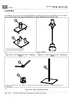
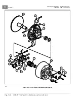
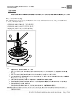
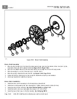
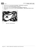
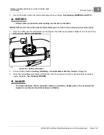
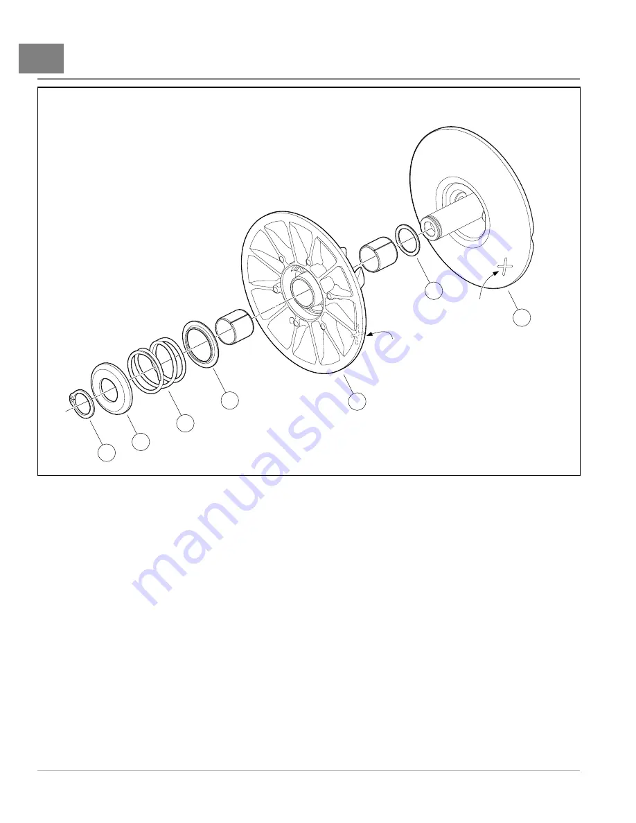
Figure 15-39
Driven Clutch Assembly
Driven Clutch Assembly
1.
Place the fixed sheave (5) onto the spring compression base and note the location of the X so the X on the
moveable sheave (4) can be aligned correctly
2.
Place the moveable sheave (4) onto the fixed sheave (5) and align the X’s on both components.
3.
Place the spring (3), cup (2), and snap ring (1) onto the clutch.
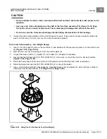
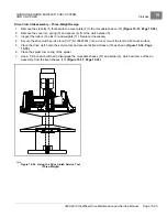
4.
Place the spring compression collar onto the cup
5.
Tighten the spring compression nut just enough to enable the snap ring to be installed.
6.
Use snap ring pliers to install the snap ring.
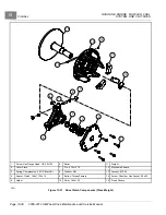
Driven Clutch Installation
1.
Install the driven clutch assembly on the transmission splined shaft.
2.
Install the mounting washer and new retaining bolt. Tighten retaining bolt to 39 ft-lb (53 N·m).
3.
Install the drive belt as instructed.
See Drive Belt Installation on page 15-31.
4.
Install the clutch outer cover and tighten the screws to 72 in-lb (8 N·m).
5.
Install the top air filter hose on the filter canister.
See following NOTE.
Page 15-40
2008-2012 All-Wheel Drive Maintenance and Service Manual
Содержание Carryall 295 SE
Страница 2: ......
Страница 20: ......
Страница 28: ......
Страница 58: ......
Страница 66: ......
Страница 100: ......
Страница 122: ......
Страница 150: ......
Страница 157: ......
Страница 190: ......
Страница 197: ......
Страница 236: ......
Страница 284: ......
Страница 386: ......
Страница 394: ......
Страница 442: ......
Страница 452: ......
Страница 454: ......
Страница 455: ......
Страница 456: ......


