Clou CL7206C8 Скачать руководство пользователя страница 8


2. Sketch map 

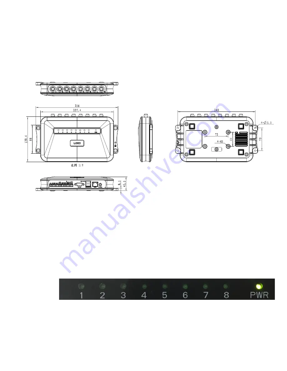
2.1 Physical construction 

Image 2-1 Structure diagram of CL7206C8 

Size: 256mm*147.6mm*43.47mm


2.2 Weight 

Main body: 1.14kg(accessories excluded) 

2.3 Illustration of LED display 


Image2-2    Sketch map of reader’s LED indicator 

LED indicator panel describe as below Form 2-1: 

Содержание CL7206C8

Страница 1: ...User Manual of CL7206C8 RFID Reader Shenzhen Clou IOT Technologies Co Ltd V2 0 4...

Страница 2: ...Welcome to be user of CLOU RFID products Thanks for choosing CLOU s Eight Port Fixed RFID Reader CL7206C8 We believe our device will bring convenience for your work...

Страница 3: ...2 3 Illustration of LED display 8 2 4 Interfaces 9 2 4 1 Power supply communication and I O interface 9 2 4 2 I O Interface definition 10 2 4 3 Feeding line optional 12 2 4 4 Network connection diagra...

Страница 4: ...4 5 3 Write data 25 4 5 4 TCP server client mode 28 4 5 5 Antenna configuration 29 4 5 6 Base band parameter configuration 30 4 5 7 Antenna port power setting 31 4 5 8 Clock setting 32 4 5 9 Frequency...

Страница 5: ...6 Package 46 6 1 Package 46 6 2 Accessories 46 6 3 Storage environment 47 7 After sale service 49...

Страница 6: ...nti interference ability good protection performance and easy installation 1 2 Technical 1 2 1 Main function Protocol support ISO18000 6C 6B standard Built in LINUX operating system Multiple communica...

Страница 7: ...nnel bandwidth 200 KHz RS232 serial communication rate 115200bps default 19200 bps 9600bps RS485 interface communication rate 115200bps default 19200 bps 9600bps Support Weigand 26 34 66 interfaces Po...

Страница 8: ...Image 2 1 Structure diagram of CL7206C8 Size 256mm 147 6mm 43 47mm 2 2 Weight Main body 1 14kg accessories excluded 2 3 Illustration of LED display Image2 2 Sketch map of reader s LED indicator LED in...

Страница 9: ...dicator Indicates antenna 5 is working ANT6 Antenna 6 indicator Indicates antenna 6 is working ANT7 Antenna 7 indicator Indicates antenna 7 is working ANT8 Antenna 8 indicator Indicates antenna 8 is w...

Страница 10: ...USB host port For external U disk wireless LAN and other expansion devices RS 232 RS 232 serial port Serial communication interface with control reader Other I O interface See detailed definition 2 4...

Страница 11: ...3 output DC_MAX 30V 2A AC_MAX 125V 0 3A logic 0 indicates the open a logic 1 means close the default is open R4 Relay output 4 DC_MAX 30V 2A AC_MAX 125V 0 3A logic 0 indicates the open a logic 1 means...

Страница 12: ...ty internal thread inner pin connector connect with reader antenna TNC connector RF cable SMA connector connect with external circular polarization antennas SMA connector cable maximum length is 5m im...

Страница 13: ...used for long distance high speed connection less than 80 m can be connected with the switcher or router through the network cable or directly connected with the PC network interface as shown in figur...

Страница 14: ...the serial line Network cable connects directly no longer than 80 meters Serial line connects directly no longer than 10 meters 4 When installing several readers the antenna position and the antenna s...

Страница 15: ...face is for short distance communication less than 10m through the DB9 connector and the PC serial port connection to realize the communication of PC and the device RJ45 network port used for long dis...

Страница 16: ...16 Whether the screws are tighten 3 5 2 Performance acceptance Whether the reader is working properly Whether the read and write range is reasonable...

Страница 17: ...have been connected to the antenna ANT ANT1 2 ANT 3 ANT totally four ports 3 If the reader and writer start up hear drop buzzer sound 4 2 Application environment The software environment Windows 2000...

Страница 18: ...be operated only after successful connection 4 5 1 1 Serial communication connection Double click the icon to start the Demo software the main interface of the toolbar icons are gray means reader is n...

Страница 19: ...uccessful 4 5 1 2 Network port communication connection Network port used for long distance connection within 80 m connect to the router through cable and switcher router or connected with the PC netw...

Страница 20: ...connection after connect successfully then you can found the current IP address through select settings senior configuration set up the IP address in Network port settings when configuration dialog po...

Страница 21: ...4 10 Image 4 10 485 communication connection RS485 address defaults to 1 RS485 address range 1 255 Note Click the button after changing the configuration 4 5 1 4 USB communication connection Select t...

Страница 22: ...o types EPC EPC data of tags can be read and write TID the TID data of the label the only logo read only User Data user data area can be read and write Reserve Data reserved area data store the passwo...

Страница 23: ...ease refer to chapter 4 5 2 3 custom read 4 5 2 2 Read TID Click the button the data display area will display the current read EPC and TID data TID data display as hexadecimal character string use th...

Страница 24: ...read the tag retains data use the word as the starting address and read length unit Image 4 13 6C Tag custom configurations Select the 6B tag configuration and pop up dialog box as shown in image 4 14...

Страница 25: ...Image 4 14 6B Tag custom configurations 4 5 2 4 Stop read Click button stop all read and write operations 4 5 3 Write data 4 5 3 1 Write EPC data Click button and pop up dialog box as shown in image 4...

Страница 26: ...e 4 15 write EPC data Select a label data contains TID information has been read fill in the EPC data 16 hex string click OK 4 5 3 2 Write user data Click button and pop up dialog box as shown in imag...

Страница 27: ...4 16 write user data Select a label data contains TID information has been read fill in the user data 16 hex string click OK 4 5 3 3 Custom tag action Click button and pop up dialog box as shown in im...

Страница 28: ...the custom operation button 3 Take detailed action to write lock destroy tag according to the reader protocol 4 5 4 TCP server client mode Select configuration on the main demo interface read and writ...

Страница 29: ...ode the connection is initiated by PC when the reader set as a client mode it will connect to the PC side automatically 4 5 5 Antenna configuration Select configuration on the DEMO main interface seni...

Страница 30: ...figure succeeds If the antenna enable is not selected when select the corresponding reader on the DEMO main interface will pop up dialogue box as shown in image 4 20 Image 4 20 Antenna selection 4 5 6...

Страница 31: ...EPC base band rate provides five options Tair 25us FM0 LHF 40KHz dense reading mode Tair 25us Miller4 LHF 300KHz fast reading mode 255 OUTO Session four choices 0 1 2 3 Q values provide sixteen option...

Страница 32: ...tion of the success of the dialog box click OK to complete power configuration 4 5 8 Clock setting Select configuration on the DEMO main interface senior reader configuration then pop up dialog box as...

Страница 33: ...ation hopping management pop up frequency hopping management dialog box as shown in image 4 24 Imag 4 24 Frequency Hopping management Select CMII 920 925MHz see Image 4 25 in the working band drop dow...

Страница 34: ...nts on the right side of the list box will be cleared Image 4 25 Frequency Band selection Note The purpose of setting up the automatic is to avoid the interference of the external signal and select th...

Страница 35: ...4 5 11 Buffer and breakpoint resume For make sure the reader s complete collection of rfid tags data CL7206C8 support tag data caching mechanism and breakpoint resume in case that the tag s data loss...

Страница 36: ...kpoint resume function the PC will reply each data of tags uploading reader will automatically save the tag s data which are not uploaded PC could operate the saved data through setting Obtain saved d...

Страница 37: ...he communication efficiency increase the system load we suggest When start the breakpoint upload functions according to your application can set up suitable tag filter parameter filter time to reduce...

Страница 38: ...enter a period of idle state to save power consumption the reader re enter the card reader automatically after idle time 4 5 13 GPI O configuration GPI O control is to provide the query and set up th...

Страница 39: ...list Description when the start condition is satisfied the reader will perform the configuration of the reader writer command GPO configuration Select configuration on the main interface GPI O config...

Страница 40: ...d port Parameter configuration includes Weigand 26 Weigand 34 and Weigand 66 models Weigand 26 TID or EPC data reported from the end of the Weigand port is valid for 3 bytes Weigand 34 TID or EPC data...

Страница 41: ...click OK button and all settings of the reader will be restored to the factory setting 4 5 15 Tools Data export Select tools on the main interface data export form XLS in the pop up dialog box as show...

Страница 42: ...re upgrades system software applications Select tools on the main interface software upgrade software the pop up dialog box as shown in image 4 33 Image 4 33 Application software upgrade To find the B...

Страница 43: ...43 Image 4 34 Software upgrade successfully The process of the application of the base band software is the same as that of the application software...

Страница 44: ...light failed when power on Check whether the communication is normal please contact customer service if it s not normal The serial port unable to connect Check if the serial cable is not connected or...

Страница 45: ...heck if the label is damaged Check if the label is placed in the reader s valid reading and writing range Check if the electromagnetic interference between the reader and the other device For the prob...

Страница 46: ...the packing material should be kept properly after unpack Besides of the device in the box accessories equipped with the reader are also included in please check the product packing list to confirm wh...

Страница 47: ...Included 4 Network cable 20350000000188 1 unit Included 5 RS232 blackcable 20351000000478 1 pcs Included 6 USB cable 20351000000036 1 pcs Included 7 9dBi circularly polarized antenna 20351000000035 8...

Страница 48: ...48 Environment temperature 40 85 Relative humidity 5 RH 95 RH...

Страница 49: ...ign of circuits without given notifications Thus the real product may be not in accordance with this manual Generally we will provide timely amendments to this manual If it s not provided timely pleas...

Страница 50: ...ard with each device please keep it to enjoy the service 1 Products can replace free under conditions within one month after sale in the precondition of normal operation without repairing 2 Free maint...

Отзывы: