


Disassembly
2 - 16 Removing and Installing a Processor
2.Disassembly
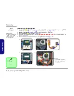
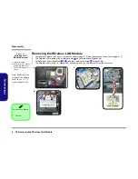
Processor Installation Procedure
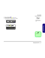
1.
Insert the CPU
(
Figure 12a
), and pay careful attention to the pin alignment; it will fit only one way (DO NOT
FORCE IT!), and turn the release latch
towards the lock symbol
(
Figure 12b
).
2.
Remove the sticker
(
Figure 12c
) from the heat sink unit (if it is a new unit).
3.
Insert the heat sink
as indicated in
Figure 12c
.
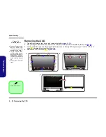
4.
Tighten the CPU heat sink screws in the order
,
, , , , ,
&
(the order as indicated on the
label and
Figure 12d
).
5.
Replace the CPU fan, component bay cover and tighten the screws (
page 2 - 14
).
A
B
C
D
1
2
3
4
5
6
7
8
4
1
7
6
3
2
5
8
b.
B
a.
D
Note
:
Tighten the screws in
the order as indicated
on the label.
A
c.
d.
C
D
C
Figure 12
Processor
Installation
a. Insert the CPU.
b. Turn the release latch to-
wards the lock symbol.
c. Insert the heat sink.
d. Tighten the screws.
A. CPU
D. Heat Sink
•
4 Screws
Содержание W670SZQ
Страница 1: ...W670SZQ ...
Страница 2: ......
Страница 3: ...Preface I Preface Notebook Computer W670SZQ Service Manual ...
Страница 24: ...Introduction 1 12 1 Introduction ...
Страница 46: ...Disassembly 2 22 2 Disassembly ...
Страница 49: ...Top A 3 A Part Lists Top Figure A 1 Top ...
Страница 50: ...A 4 Bottom A Part Lists Bottom Figure A 2 Bottom ...
Страница 51: ...COMBO A 5 A Part Lists COMBO 非耐落 Figure A 3 COMBO ...
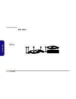
Страница 52: ...A 6 DVD DUAL A Part Lists DVD DUAL Figure A 4 DVD DUAL 非耐落 ...
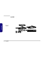
Страница 53: ...HDD A 7 A Part Lists HDD Figure A 5 HDD ...
Страница 54: ...A 8 2nd HDD A Part Lists 2nd HDD Figure A 6 2nd HDD ...
Страница 55: ...LCD A 9 A Part Lists LCD Figure A 7 LCD ...
Страница 56: ...A 10 A Part Lists ...
Страница 104: ...Schematic Diagrams B 48 B Schematic Diagrams ...


