Disassembly
2 - 14 Removing and Installing a Processor
2.Disassembly
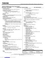
5.
Turn the release latch
towards the unlock symbol
to release the CPU (
Figure 10f
).
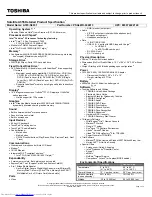
6.
Carefully (it may be hot) lift the CPU
up and out of the socket (
Figure 10g
).
7.
Reverse the process to install a new CPU.
8.
When re-inserting the CPU, pay careful attention to the pin alignment, it will fit only one way (DO NOT FORCE IT!)
C
D
d.
D
C
e.
C
Caution
The heat sink, and CPU area in
general, contains parts which are
subject to high temperatures. Allow
the area time to cool before remov-
ing these parts.
D. CPU
Figure 10
Processor Removal
(cont’d)
d. Turn the release latch to
unlock the CPU.
e. Lift the CPU out of the
socket.
Содержание P670SG
Страница 1: ...P670SG ...
Страница 2: ......
Страница 3: ...Preface I Preface Notebook Computer P670SG Service Manual ...
Страница 24: ...Introduction 1 12 1 Introduction ...
Страница 48: ...Disassembly 2 24 2 Disassembly ...
Страница 51: ...Top A 3 A Part Lists Top Figure A 1 Top ...
Страница 52: ...A 4 Bottom A Part Lists Bottom Figure A 2 Bottom ...
Страница 53: ...MB A 5 A Part Lists MB 㓦㬌ỵ伖 Figure A 3 MB ...
Страница 54: ...A 6 HDD A Part Lists HDD Figure A 4 HDD ...
Страница 55: ...LCD A 7 A Part Lists LCD Figure A 5 LCD ...
Страница 56: ...A 8 A Part Lists ...
Страница 128: ...Schematic Diagrams B 72 B Schematic Diagrams ...