Disassembly
Removing the Optical Device 2 - 19
2.Disassembly
Removing the Optical Device
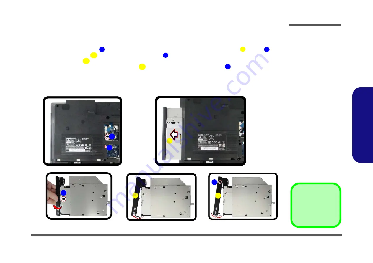
Figure 14
ODD Removal
a. Remove the screw.
b. Push the optical device
out of the computer.
c. Pry the bezel off the opti-
cal device.
d. Separate the bezel and
optical device
e. Install the front bezel.
1.
Turn
off
the computer, turn it over, and remove the battery (
) and the component bay cover (
).
2.
Remove the screw at point
, and use a screwdriver to carefully push out the optical device
at point
.
3.
Carefully pry the bezel
off the optical device at point
(
)
.
4.
Separate the bezel
and the optical device as shown (
).
5.
Reverse the process to attach the front bezel
with the new optical device at point
(
).
6.
Insert the new device and carefully slide it into the computer (the device only fits one way. DO NOT FORCE IT; The
screw holes should line up). Replace the bottom cover and tighten the screws.
7.
Restart the computer to allow it to automatically detect the new device.
1
3
2
5
4
5
5
6
b.
a.
2
3
1
e.
c.
d.
4
6
5
5
3. Optical Device
5. Bezel Cover
•
1 Screws
Содержание N350TW
Страница 1: ...N350TW ...
Страница 2: ......
Страница 3: ...Preface I Preface Notebook Computer N350TW Service Manual ...
Страница 24: ...Introduction 1 12 1 Introduction ...
Страница 47: ...Top A 3 A Part Lists Top Figure A 1 Top ...
Страница 48: ...A 4 Bottom A Part Lists Bottom Figure A 2 Bottom ...
Страница 49: ...DVD A 5 A Part Lists DVD Figure A 3 DVD ...
Страница 50: ...A 6 LCD A Part Lists LCD Figure A 4 LCD ...
Страница 51: ...MB A 7 A Part Lists MB Figure A 5 MB ...
Страница 52: ...A 8 A Part Lists ...
Страница 110: ...Schematic Diagrams B 58 Power On Sequence B Schematic Diagrams ...


