Page 5
823036EN
02/11/2014
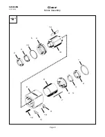
Invert the motor housing and install the rotor with the
end stamped “REAR” into the rear rotor bearing.
Insert the six (6) rotor blades into the rotor. Lubricate
the o-rings on the front bearing plate and press this
assembly into the motor housing.
Note: Make sure the
o-ring (863096) is installed on the front bearing plate.
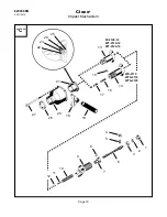
Impact Mechanism Assembly:
Put a light coating of 30W oil on all parts before
assembling.
Insert the timing pin into the recess located on the small
O.D. of the cam. Install the cam and pin into the rear of
the hammer.
Install the cam roller shaft into the cam shaft and slide
the cam roller over the cam roller shaft. Place the butt
plate, insulator and shock absorber onto the rear of the
cam shaft.
Hold the cam shaft vertically on the work bench with
the shock absorber down and tap the end of the cam
shaft with a soft mallet to seat the cam shaft in the shock
absorber. Insert the cam shaft assembly through the
cam and hammer assembly.
Install the hammer spring, anvil pin and spring clip onto
the front of the cam shaft and hammer assembly. Rotate
the spring clip to accept the anvil pin and then install the
anvil on top of the assembly. Make sure the slot in the
anvil lines up with the anvil pin. Drive the anvil down until
the spring clip engages the recess in the anvil.
Spline Drive Models: Insert the socket retainer spring
and socket retainer plunger into the anvil and then drive
the socket retainer pin radially into the plunger.
Anvil Housing Assembly:
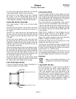
If the anvil housing bushing requires replacement it
should be pressed in as shown below.
General Assembly:
Put a light coating of 30W oil on the hammer and rotor
splines. Insert the impact mechanism into the front of the
rotor. Lubricate the anvil housing seal and bushing with
30W oil and install on the unit. Make sure the contour of
the anvil housing matches the motor housing.
The anvil and hammer lugs should be in line with the
recess in the make-up lip located in the anvil housing.
Install the dead handle bracket on the left side of the tool
and insert the four housing bolts. Lightly tap the bolts
with a hammer until the anvil housing seats against the
motor housing.
Clamp the tool vertically in a smooth jawed vise and
install the gasket. Insert the o-ring (847981) into the
reversing valve bore and install the reversing valve.
Apply a thin coating of grease to the motor clamp seal
(869001) and place it into the handle recess.
Assemble the handle to the tool using the four (4) nuts.
Tighten the nuts to 20 ft. lbs. torque.
Lay the tool on its right side and remove the 30W oil fill
plug. Fill the reservoir with a good grade of 30W oil up to
the level of the fill indicator pin located in the reservoir,
approximately 1 to 1.25 fluid ounces.
Place a couple of teaspoons of 10W machine oil in the
air inlet bushing before attaching the air hose. This will
insure immediate lubrication of all motor components.
Disposal:
Observe local disposal guidelines for all
components of this tool and its packaging.
Copyright Protection:
Apex Tool Group, LLC or Apex Tool Group GmbH &
Co. OHG reserves the right to modify, supplement or
improve this document or the product without prior
notice. This document may not be reproduced in any
way, shape or form, in full or parts thereof, or copied to
another natural or machine readable language or to a
data carrier, whether electronic, mechanical, optical or
otherwise without the express permission of Apex Tool
Group, LLC or Apex Tool Group GmbH & Co. OHG
Press on this O.D. only
Press on this O.D. only
Cleco
®
Product Information

