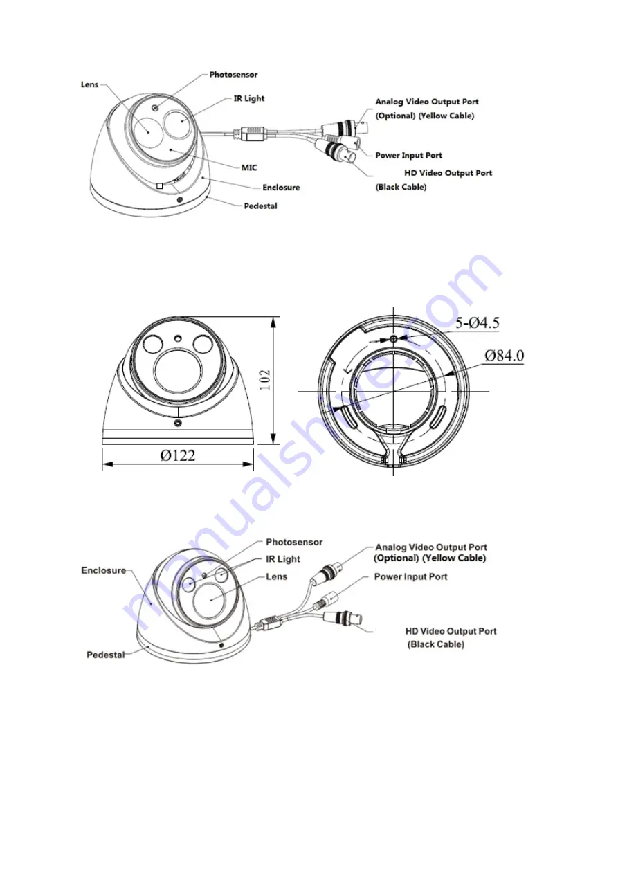
5
Figure 2-10
See Figure 2-11 for the dimension of
model F.
Figure 2-11
See Figure 2-12 for the structure components of
Figure 2-12
See Figure 2-13 for the cable of single channel video output.
Страница 1: ...HDAVS Camera User s Manual Version 1 0 0 ...
Страница 2: ...i Table of Contents 1 General Introduction 1 1 1 Overview 1 1 2 Features 1 2 Device Framework 2 3 Installation 7 4 Menu 12 4 1 HAVR Settings 12 4 2 Menu Operation 12 Appendix Ⅰ Maintenance 14 ...
Страница 3: ... the plug power socket and the junction from the device 2 Environment Please don t aim the device at strong light such as lighting sunlight and so on to focus Please transport use and store the device within the range of allowed humidity and temperature Please do not allow water and other liquid falling into the camera in case that the internal components are damaged Please keep the sound ventilat...
Страница 4: ... manual will be regularly upgraded according to the product update the upgraded content will be added in the manual without prior announcement Please contact the customer service for the latest procedure and supplementary documentation The company is not liable for any loss caused by the operation which is not followed by the manual Please refer to the company s final explanation if there is any d...
Страница 5: ...P series support 75 3 coaxial cable transmission without any loss The distance is over 500m High speed long distance real time transmission Support HDAVS HD video and analog video output Support 3D noise reduction excellent low illuminance performance Support ICR switch to realize surveillance both in the daytime and at night Support OSD menu adjustment parameters Support smart IR function Support...
Страница 6: ...Figure 2 1 for the dimension of model A Figure 2 1 See Figure 2 2 for the structure components of model A Figure 2 2 See Figure 2 3 for the dimension of model B Figure 2 3 See Figure 2 4 for the structure components of model B ...
Страница 7: ...3 Figure 2 4 See Figure 2 5 for the dimension of model C Figure 2 5 See Figure 2 6 for the structure components of model C Figure 2 6 See Figure 2 7 for the dimension of model D ...
Страница 8: ...4 Figure 2 7 See Figure 2 8 for the structure components of model D Figure 2 8 See Figure 2 9 for the dimension of model E Figure 2 9 See Figure 2 10 for the structure components of model E ...
Страница 9: ...5 Figure 2 10 See Figure 2 11 for the dimension of model F Figure 2 11 See Figure 2 12 for the structure components of model F Figure 2 12 See Figure 2 13 for the cable of single channel video output ...
Страница 10: ...eo signal by default it needs to enable self adaptation function in the OSD menu to switch to standard definition video signal See Figure 2 14 for the dual power cable Figure 2 14 Note Camera models with dual power use the cable structure shown in Figure 2 13 the power input port supports DC12V AC24V power supply ...
Страница 11: ...thick enough to sustain at least 3X weight of the camera For the installation mode of side outlet make sure the direction of side outlet is in accordance with that of the installation position map when sticking the installation position map Besides pull the cable through the pedestal cable slot before locking the screw Please refer to the following installation steps if it is model A B or C Figure...
Страница 12: ...e body enclosure or compression cover and the decoration ring according to different models Model A Close the buckle rotate the enclosure and dome body to proper monitoring location and finally rotate the decoration ring tightly Model B Rotate the decoration ring and fix it preliminarily then rotate the compression cover and dome body to proper monitoring location finally rotate the decoration rin...
Страница 13: ... bolts into the installation holes Step 4 Adjust the pedestal location pull the cable through side cable slot if it is side cable outlet Align the bolt fixing hole of device pedestal with the expansion bolt fixing holes of the installation surface insert the self tapping screws into the expansion bolts and secure them firmly to fix the pedestal on the installation surface if it is top outlet pull ...
Страница 14: ...the installation surface according to the installation position map Step 3 Use tools to fix the expansion bolts into the installation holes Step 4 Adjust the pedestal location pull the cable through side cable slot if it is side cable outlet Align the bolt fixing hole of device pedestal with the expansion bolt fixing holes of the installation surface insert the self tapping screws into the expansi...
Страница 15: ...power Step 7 Adjust the lens zoom and focus via back end coding device to make image clear So far you have completed the device installation and cable connection you can check the monitoring image via back end coding device ...
Страница 16: ...nu Setting System PTZ you need to select the channel number for access and set control mode as HDAVS and the protocol as HD AVS Click Save button to save current setup See Figure 4 1 Figure 4 1 4 2 Menu Operation Click the right mouse button and select PTZ Control then you will see the PTZ Setup menu which is as shown in Figure 4 2 and Figure 4 3 Figure 4 2 ...
Страница 17: ...ens zoom and auto trigger focus Note Some of the buttons can only be applied for the motorized vari focal camera Adjust lens focus Auto focus under current zoom rate Lens reset Sheet 4 1 If there is click the Confirm button in Menu Operation interface to go to the 2nd menu Click Return button to go back to the previous menu interface ...
Страница 18: ...cloth and wipe several times if it is not clean enough Camera Body Maintenance Use a soft dry cloth to clean the camera body when it is dirty in case the dirt is hard to remove use a clean dry cloth soaked with mild detergent and wipe gently make it dry later Don t use volatile solvent like alcohol benzene thinner and etc or strong detergent with abrasiveness otherwise it will damage the surface c...
Страница 19: ... here are subject to change without prior written notice All trademarks and registered trademarks mentioned are the properties of their respective owners If there is any uncertainty or controversy please refer to the final explanation of us Please visit our website or contact your local service engineer for more information ...