background image

28

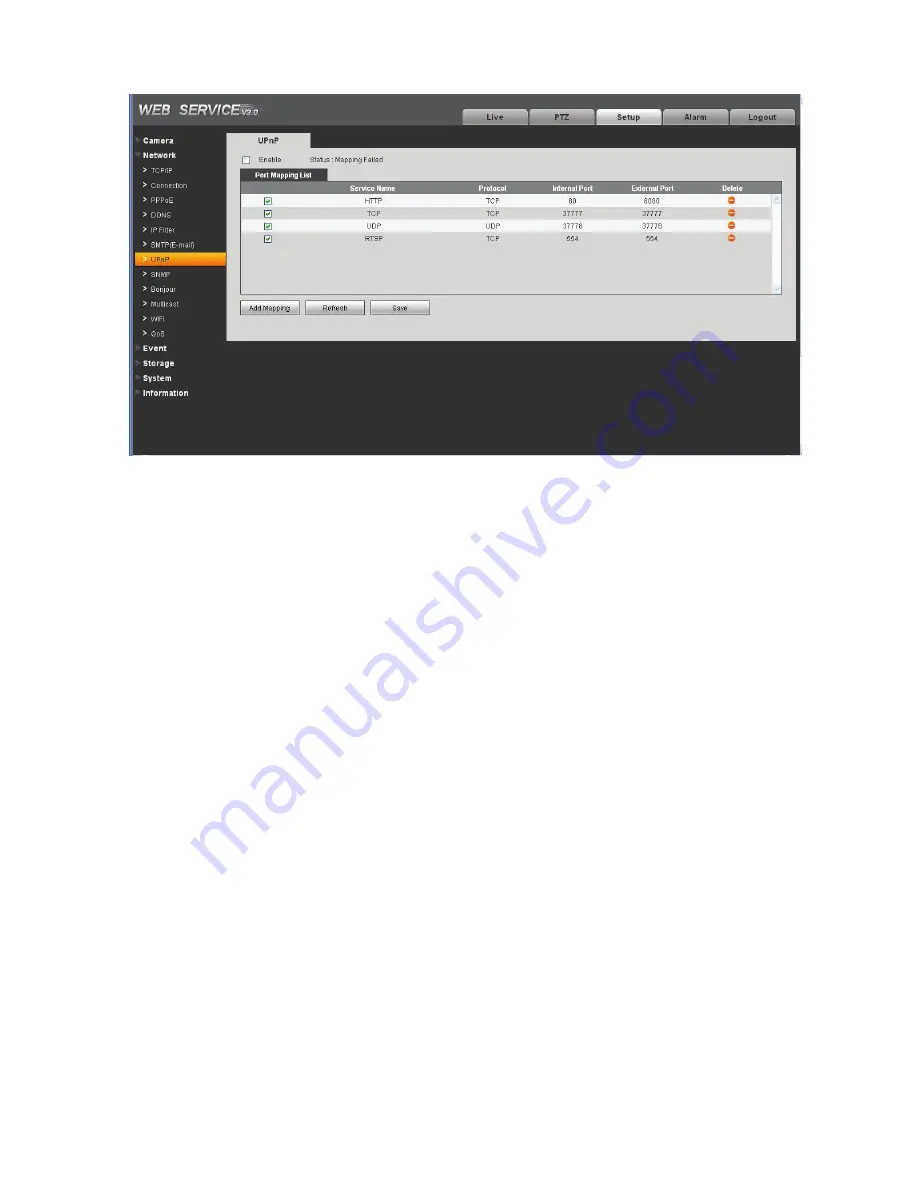
Figure 4-13 

4.2.8 SNMP 

The SNMP interface is shown as in Figure 4-14. 

The SNMP allows the communication between the network management work station software and the 

proxy of the managed device. Please install the software such as MG MibBrowser 8.0c software or 

establish the SNMP service before you use this function. You need to reboot the device to activate the 

new setup.

Содержание 834IP71

Страница 1: ...Mini IP Dome Camera Version 1 1 0 ...

Страница 2: ...n the SELV Safety Extra Low Voltage and the Limited power source is rated 12V DC in the IEC60950 1 We assume no liability or responsibility for all the fires or electrical shock caused by improper handling or installation We are not liable for any problems caused by unauthorized modification or attempted repair 2 Transportation security Heavy stress violent vibration or water splash are not allowe...

Страница 3: ... adopted to better prevent thunder The grounding holes of the product are recommended to be grounded to further enhance the reliability of the camera 6 Daily Maintenance Please shut down the device and then unplug the power cable before you begin daily maintenance work Do not touch the CCD CMOS optic component You can use the blower to clean the dust on the lens surface Always use the dry soft clo...

Страница 4: ...Quick Start Guide Accessory Name Amount IPC Unit 1 Accessories bag 1 Quick Start Guide 1 CD 1 Quick Start Guide 03 ...

Страница 5: ...stallation 08 2 1 Device Installation 08 2 2 SO Card Installation 10 3 Quick Configuration Tool 12 3 1 Overview 12 3 2 Operation 12 4 Web Operation 15 4 1 Network Connection 15 4 2 Login and Logout 15 Appendix Toxic or Hazardous Materials or Elements 19 Mini IP Dome Camera 04 ...

Страница 6: ...1 1 Dimensions Please refer to the following figure for the dimension information The unit is mm See Figure 1 1 through Figure 1 3 Figure 1 1 Rl 75 R2 6 Figure 1 2 Quick Start Guide 05 ...

Страница 7: ...Figure 1 3 1 2 Structure Please refer to the following figure for detailed information See Figure 1 4 Figure 1 4 Mini IP Dome Camera 06 CD ...

Страница 8: ...heet for detailed information SN Name 1 X Y Z rotation module 2 Device lens 3 Dome camera enclosure SN Name Function 4 Power input port Connect to the DC 12 power to input the power 5 Network port Network data input output and PoE Quick Start Guide 07 ...

Страница 9: ... on the table to realize surveillance Or you can use the bracket or the in ceiling installation to realize the hang function Please refer to the steps listed below Dome camera body u Enclosure secure screws Figure 2 1 lnnerhexagona wrench Figure 2 2 Mini IP Dome Camera 08 ...

Страница 10: ...talling the device cable And then you can draw out the cable from the cable channel of the pedestal St Adjust the dev1ce installation pedestal to the proper position and then draw the cable through the cable exit you just dug in the ceiling wall Line up the TOP direction of the device to the installation position map and then line up the three screw holes in the device pedestal to the three plasti...

Страница 11: ...D screw specification is M3 See Figure 2 3 2 2 SO Card Installation Important 0 Figure 2 3 Some series product do not support the SO card storage function Please shut down the power and then turn off the device before you install the SO card Step 1 Please refer to the step 1 in chapter 2 1 to open the device Step 2 Find the SO CARD indicator in the enclosure Adjust the SO card to the proper direct...

Страница 12: ... Quick Start Guide Figure 2 4 Quick Start Guide 11 ...

Страница 13: ...ConfigToois exe icon you can see an interface is shown as in Figure 3 1 In the device list interface you can view device IP address port number subnet mask default gateway MAC address and etc lli n i I H n i I r 1M I f l ji i 1 iii f 1 n k t n j h _ 1 h c r L r ll i t _p r b i n fl J I f 1 1 t Y t i I C l Figure 3 1 OCr 1 r i l tY t J l ifi 1 Select one IP address and then right click mouse you ca...

Страница 14: ...1 00 15 16 f lt 7 1 i i 77 7 7 S 1 r t i 0 1 7 C C 5 fi 37 t f h J e iiiJ ttJIII f S if llrr _ p J R _ 1C t c 1 J p_ r P 1 ur t r f nJ i id I I t 1 1 1 1 C 5 d1 k l t Jr f 1 r i rr f lj t n q t 1 r r 1 h L 4 l t L t rn _ f l n h Figure 3 2 Select the Open Device Web item you can go to the corresponding web login interface See Figure 3 3 Figure 3 3 Quick Start Guide 13 ...

Страница 15: ...o to the login interface See Figure 3 4 In Figure 3 4 you can view device IP address user name password and port Please modify the corresponding information to login Please note the port information here shall be identical with the port value you set in TCP port in Web Network interface Otherwise you can not login the device If you are use device background upgrade port 3800 to login other setups ...

Страница 16: ...ction Please follow the steps listed below for network connection Make sure the IPC has connected to the network properly Please set the IP address subnet mask and gateway of the PC and the IPC respectively IPC default IP address is 192 168 1 108 Subnet mask is 255 255 255 0 Gateway is 192 168 1 1 Use order ping IP camera address to check connection is OK or not 4 2 Login and Logout Open IE and in...

Страница 17: ...ow See Figure 4 2 Please input your user name and password Default factory name is admin and password is admin Input your IP address here Note For security reasons please modify your password after you first login t rtt e F orll es t e Figure 4 2 Min1IP Dome Camera 16 ...

Страница 18: ...ms Ad anced 3 f H ir i i j Internet Locoltltronet Trusted sites v Internet Th zone Is for Internet webSitcs except trnse losted n trusted ond re trlc tecf zones Allwed levels for th zcno Medum to HIQh MediUm t gh J Appropn e for most webs tes Prompts before downOadwl l pcJtert aly cmafe content Unsq ed Act veX cootrols rd be OO nloocied Disable i Enoble Download siQned ActiveX control rd secure Ol...

Страница 19: ...ra After you logged in you can see the main window See Figure 4 4 Se Cr F VOrltes Figure 4 4 Please refer to the Web Operation Manual included in the resource CD for detailed operation instruction Mini IP Dome Camera 18 ...

Страница 20: ...ndicates that the concentration of the hazardous substance of at least one of all homogeneous materials in the parts is above the relevant threshold of the SJ T11363 2006 standard During the environmental friendly use period EFUP period the toxic or hazardous substance or elements contained in products will not leak or mutate so that the use of these substances or elements will not result in any s...

Страница 21: ...in user interface All the designs and software here are subject to change without prior written notice If there is any uncertainty or controversy please refer to the final explanation of us Please visit our website or contact your local service engineer for more information Mini IP Dome Camera 20 ...

Страница 22: ...f ...

Страница 23: ...HD IR Waterproof Fixed IP Dome Camera Quick Start Guide Version 1 0 0 ...

Страница 24: ...r installation We are not liable for any problems caused by unauthorized modification or attempted repair 2 Transportation security Heavy stress violent vibration or water splash are not allowed during transportation storage and installation 3 Installation Do not apply power to the camera before completing installation Please install the proper power cut off device during the installation connecti...

Страница 25: ... use the dry soft cloth to clean the device If there is too much dust please use the water to dilute the mild detergent first and then use it to clean the device Finally use the dry cloth to clean the device Please put the dustproof cap to protect the CCD CMOS component when you do not use the camera 7 Accessories Be sure to use all the accessories recommended by manufacturer Before installation p...

Страница 26: ...UN DQG LPHQVLRQ 1 HYLFH QVWDOODWLRQ 3 QVWDOODWLRQ 6WHSV 3 5HVWRUH DFWRU HIDXOW 6HWXS QWURGXFWLRQ 5 4XLFN RQILJXUDWLRQ 7RRO 6 2YHUYLHZ 6 2SHUDWLRQ 6 HE 2SHUDWLRQ 9 1HWZRUN RQQHFWLRQ 9 RJLQ DQG RJRXW 9 4 12 SSHQGL 7R LF RU D DUGRXV 0DWHULDOV RU OHPHQWV 13 ...

Страница 27: ...1 1 Figure 1 1 Please refer to the following sheet for detailed information Port Name Function Note Port 4 Network port Connect to standard Ethernet cable Port 5 DC 12V power Power input port Input DC 12V UDPHZRUN DQG LPHQVLRQ Component Component Name Component 1 Device lens Component 2 Dome body Component 3 Dome enclosure ...

Страница 28: ...2 Please refer to the following two figures for dimension information The unit is mm See Figure 1 2 and Figure 1 3 Figure 1 2 Figure 1 3 ...

Страница 29: ...l the device Step 3 Adjust the device installation pedestal to the proper position and then line up the three screw holes in the device pedestal to the three plastic expansion bolt holes in the installation position Put the three self tapping screws in the three plastic expansion bolts firmly Loosen the M3X8 cross recessed pan head slot screw of the pedestal to unfasten the preforming Do not remov...

Страница 30: ...the other is from the side Please refer to the following figure for cable exit from the side information Figure 2 3 Please earth the GND port of the device to enhance the device reliability The GND port is near the cable exit port on the rear of the dome The GND screw uses the M2X5 pan screw ...

Страница 31: ...gland cover Step2 Take the dome body out and then turn the top cover hard to remove Step3 Slightly press the RESET button to complete the reset function See Figure 2 5 Step4 Turn the top cover back to the original position Please make sure it reaches the original position otherwise it may result in water leakage Step5 Put the dome back to the gland cover Please refer to step4 in chapter 2 1 to ins...

Страница 32: ...address and etc Figure 3 1 Select one IP address and then right click mouse you can see an interface is shown as in Figure 3 2 Note You can set the IP address subnet mask and gateway for the IPC and PC Please note IPC IP address and PC IP address shall be in the same network segment if there is no router IPC default IP address is 192 168 1 108 If there is a router please set the corresponding gate...

Страница 33: ... IP address and then double click it to open the login interface Or you can select an IP address and then click the Login button to go to the login interface See Figure 3 4 In Figure 3 4 you can view device IP address user name password and port Please modify the corresponding information to login Please note the port information here shall be identical with the port value you set in TCP port in W...

Страница 34: ...guration tool main interface is shown as below See Figure 3 5 Figure 3 5 For detailed information and operation instruction of the quick configuration tool please refer to the Quick Configuration Tool User s Manual included in the resources CD ...

Страница 35: ...IPC default IP address is 192 168 1 108 Subnet mask is 255 255 255 0 Gateway is 192 168 1 1 z Use order ping IP camera address to check connection is OK or not RJLQ DQG RJRXW Open IE and input IP camera address in the address bar For example if your camera IP is 192 168 1 108 then please input http 192 168 1 108 in IE address bar See Figure 4 1 Figure 4 1 The login interface is shown as below See ...

Страница 36: ...ase click OK button system can automatically install the control When system is upgrading it can overwrite the previous Web too If you can t download the ActiveX file please check whether you have installed the plug in to disable the control download Or you can lower the IE security level See Figure 4 3 Figure 4 3 After you logged in you can see the main window See Figure 4 4 ...

Страница 37: ...11 Figure 4 4 Please refer to the Web Operation Manual included in the resource CD for detailed operation instruction ...

Страница 38: ...f you can not install the client end or can not view after the installation We recommend the win2000sp4 OS or install the client end of the low version The Active X control is blocked The display card version shall be dx8 1 or higher Network connection error occurred Invalid network setup Invalid user name or password I can not play the download file There is no player There is no DX8 1 or higher ...

Страница 39: ...period the toxic or hazardous substance or elements contained in products will not leak or mutate so that the use of these substances or elements will not result in any severe environmental pollution any bodily injury or damage to any assets The consumer is not authorized to process such kind of substances or elements please return to the corresponding local authorities to process according to you...

Страница 40: ...HD IR Waterproof Fixed IP Dome Camera User s Manual Version 1 0 0 ...

Страница 41: ... our IP camera This user s manual is designed to be a reference tool for your system Please read the following safeguard and warnings carefully before you use this series product Please keep this user s manual well for future reference ...

Страница 42: ...ower cut off device during the installation connection Always follow the instruction guide the manufacturer recommended 4 Qualified engineers needed All the examination and repair work should be done by the qualified service engineers We are not liable for any problems caused by unauthorized modifications or attempted repair 5 Environment This series IP camera should be installed in a cool dry pla...

Страница 43: ...device Finally use the dry cloth to clean the device Please put the dustproof cap to protect the CCD CMOS component when you do not use the camera 7 Accessories Be sure to use all the accessories recommended by manufacturer Before installation please open the package and check all the components are included Contact your local retailer ASAP if something is broken in your package Accessory Name Amo...

Страница 44: ...XS 3 6WUXFWXUH 8 RPSRQHQWV 8 UDPHZRUN DQG LPHQVLRQ 8 HYLFH QVWDOODWLRQ 10 QVWDOODWLRQ 6WHSV 10 5HVWRUH DFWRU HIDXOW 6HWXS QWURGXFWLRQ 12 4XLFN RQILJXUDWLRQ 7RRO 13 2YHUYLHZ 13 2SHUDWLRQ 13 HE 2SHUDWLRQ 16 1HWZRUN RQQHFWLRQ 16 RJLQ DQG RJRXW 16 4 19 SSHQGL 7R LF RU D DUGRXV 0DWHULDOV RU OHPHQWV 20 ...

Страница 45: ...ckup function in accordance with your configuration and setup in alarm or schedule setting z Support record via Web and the recorded file are storage in the client end PC z Support network storage function such as FTP Network Monitor z IPC supports one channel video data transmit to network terminal and then decode Delaying time is within 270ms network bandwidth support needed z Max supports 20 co...

Страница 46: ...s Video Frame Rate NTSC Main stream 1280 960 15fps ˈ extra stream 352 240 15fps Main stream 1280 720 30fps ˈ extra stream 352 240 30fps Video Bit Rate H 264 56Kbps 8192Kbps MJPEG is adjustable and bit rate is adjustable Support customized setup Video Flip Support mirror Support flip function Snapshot Max 1f s snapshot File extension name is JPEG Privacy Mask Supports max 4 privacy mask zones Video...

Страница 47: ...ime it may result in device damage Power Consumption 4W MAX Working Temperature 10ć 60ć Working Humidify 10 90 Dimensions mm 113h86 Weight 280g Excluding box General Parameter Installation Fixed on the wall ceiling and etc DFWRU HIDXOW 6HWXS Please refer to the following sheet for factory default setup information Default Setup Setup Item IPC HDW2100P N Series Brightness 50 Contrast 50 Hue 50 Satu...

Страница 48: ...R Recommend ed Bit 192 1024Kb S Bit Rate 1024 Sub Stream I Frame interval 50 Snapshot Type General Image Size 720P 1280 720 Quality 5 Snapshot Interval 1s Privacy Mask Disable Channel Title Enable Video Overlay Time Title Enable Snapshot Path C PictureDownload Path Record Path C RecordDownload Host Name IPC Ethernet Card Wire Default Mode Static Mac Address Device MAC address when it is shipped ou...

Страница 49: ... Port 37778 HTTP Port 80 Connection RTSP Port 554 Enable Disable Username none PPPoE Password N A Server Type DisableˈCN99 DDNS Server IP none Server Port 80 Domain Name none User none Password DDNS Update Period 5 minutes IP Filter Trusted sites Disable SMTP Server none Port 25 Anonymity Disable User Name anonymity Password Sender none Authenticatio n Encryption mode N A SMTP Email Title Subject ...

Страница 50: ...r Name Device factory SN Multicast Address 239 255 42 42 Multicast Port 36666 Real time Monitor 0 QoS Command 0 Enable Disable Anti dither 5 seconds Sensitivity 3 Record Channel Enable Record Delay 10 seconds Send Email Disable Motion Detect Snapshot Disable Enable Disable Record Channel Enable Record Delay 10 seconds Send Email Disable Video detect Video Masking Snapshot Disable Enable Disable Re...

Страница 51: ...rage Record Control Bit Stream Main Stream Device No Device MAC address Language English Local Host Video Standard NTSC Date Format Y M D Time Format 24H Time Zone GMT 08 00 System Time Sync DST Disable DST Type Week Start Time 00 00 00 of the first Sunday of the month End Time 00 00 00 of the second Monday of the month NTP Disable NTP Server clock isc org Port 37 General Date and time Update Peri...

Страница 52: ...2 1 Figure 2 1 Please refer to the following sheet for detailed information Port Name Function Note Port 4 Network port Connect to standard Ethernet cable Port 5 DC 12V power Power input port Input DC 12V UDPHZRUN DQG LPHQVLRQ Component Component Name Component 1 Device lens Component 2 Dome body Component 3 Dome enclosure ...

Страница 53: ...9 Please refer to the following two figures for dimension information The unit is mm See Figure 2 2 and Figure 2 3 Figure 2 2 Figure 2 3 ...

Страница 54: ...ll the device Step 3 Adjust the device installation pedestal to the proper position and then line up the three screw holes in the device pedestal to the three plastic expansion bolt holes in the installation position Put the three self tapping screws in the three plastic expansion bolts firmly Loosen the M3X8 cross recessed pan head slot screw of the pedestal to unfasten the preforming Do not remo...

Страница 55: ...the other is from the side Please refer to the following figure for cable exit from the side information Figure 3 3 Please earth the GND port of the device to enhance the device reliability The GND port is near the cable exit port on the rear of the dome The GND screw uses the M2X5 pan screw ...

Страница 56: ...gland cover Step2 Take the dome body out and then turn the top cover hard to remove Step3 Slightly press the RESET button to complete the reset function See Figure 3 5 Step4 Turn the top cover back to the original position Please make sure it reaches the original position otherwise it may result in water leakage Step5 Put the dome back to the gland cover Please refer to step4 in chapter 3 1 to ins...

Страница 57: ...address and etc Figure 4 1 Select one IP address and then right click mouse you can see an interface is shown as in Figure 4 2 Note You can set the IP address subnet mask and gateway for the IPC and PC Please note IPC IP address and PC IP address shall be in the same network segment if there is no router IPC default IP address is 192 168 1 108 If there is a router please set the corresponding gate...

Страница 58: ... IP address and then double click it to open the login interface Or you can select an IP address and then click the Login button to go to the login interface See Figure 4 4 In Figure 4 4 you can view device IP address user name password and port Please modify the corresponding information to login Please note the port information here shall be identical with the port value you set in TCP port in W...

Страница 59: ...iguration tool main interface is shown as below See Figure 4 5 Figure 4 5 For detailed information and operation instruction of the quick configuration tool please refer to the Quick Configuration Tool User s Manual included in the resources CD ...

Страница 60: ...IPC default IP address is 192 168 1 108 Subnet mask is 255 255 255 0 Gateway is 192 168 1 1 z Use order ping IP camera address to check connection is OK or not RJLQ DQG RJRXW Open IE and input IP camera address in the address bar For example if your camera IP is 192 168 1 108 then please input http 192 168 1 108 in IE address bar See Figure 5 1 Figure 5 1 The login interface is shown as below See ...

Страница 61: ...ase click OK button system can automatically install the control When system is upgrading it can overwrite the previous Web too If you can t download the ActiveX file please check whether you have installed the plug in to disable the control download Or you can lower the IE security level See Figure 5 3 Figure 5 3 After you logged in you can see the main window See Figure 5 4 ...

Страница 62: ...18 Figure 5 4 Please refer to the Web Operation Manual included in the resource CD for detailed operation instruction ...

Страница 63: ...f you can not install the client end or can not view after the installation We recommend the win2000sp4 OS or install the client end of the low version The Active X control is blocked The display card version shall be dx8 1 or higher Network connection error occurred Invalid network setup Invalid user name or password I can not play the download file There is no player There is no DX8 1 or higher ...

Страница 64: ...ndly use period EFUP period the toxic or hazardous substance or elements contained in products will not leak or mutate so that the use of these substances or elements will not result in any severe environmental pollution any bodily injury or damage to any assets The consumer is not authorized to process such kind of substances or elements please return to the corresponding local authorities to pro...

Страница 65: ...IPC Web3 0 Operation Manual Version 3 0 2 ...

Страница 66: ...HQX 5 9LGHR LQGRZ XQFWLRQ 2SWLRQ 5 9LGHR LQGRZ 6HWXS 6 37 RQWURO 8 6HWXS 11 DPHUD 11 4 1 1 Conditions 11 4 1 2 Video 14 4 1 3 Audio 19 1HWZRUN 20 4 2 1 TCP IP 20 4 2 2 Connection 22 4 2 3 PPPoE 23 4 2 4 DDNS 23 4 2 5 IP filter 24 4 2 6 SMTP e mail 25 4 2 7 UPnP 27 4 2 8 SNMP 28 4 2 9 Bonjour 30 4 2 10 Multicast 30 ...

Страница 67: ...ation 44 4 4 3 Record control 47 6 VWHP 48 4 5 1 General 48 4 5 2 Account 50 4 5 3 PTZ 54 4 5 4 Default 54 4 5 5 Import Export 55 4 5 6 Auto maintenance 55 4 5 7 Firmware update 56 QIRUPDWLRQ 56 4 6 1 Version 56 4 6 2 Log 57 ODUP 59 RJ RXW 60 Important The following functions are for reference only Some series products may not support all the functions listed below ...

Страница 68: ...system configuration alarm and etc Please follow the steps listed below for network connection z Make sure the IPC has connected to the network properly z IPC IP address and PC IP address shall be in the same network segment If there is router please set the corresponding gateway and subnet mask z Use order ping IP camera address to check connection is OK or not ...

Страница 69: ...08 then please input http 192 168 1 108 in IE address bar See Figure 2 1 Figure 2 1 IE The login interface is shown as below See Figure 2 2 Please input your user name and password Default factory name is admin and password is admin Note For security reasons please modify your password after you first login Input your IP address here ...

Страница 70: ...ab or not Please click OK button system can automatically install the control When system is upgrading it can overwrite the previous Web too If you can t download the ActiveX file please check whether you have installed the plug in to disable the control download Or you can lower the IE security level See Figure 2 3 Figure 2 3 Security Settings ...

Страница 71: ...window See Figure 2 4 Figure 2 4 Live Interface There are four sections z Section 1 Encode setup bar z Section 2 System menu z Section 3 Window function option bar z Section 4 Window adjust bar QFRGH 6HWXS The encode setup interface is shown as in Figure 2 5 ķ ĺ ĸ Ĺ ...

Страница 72: ...e dropdown list There are three options TCP UDP Multicast 6 VWHP 0HQX System menu is shown as in Figure 2 6 Please refer to chapter 2 2 Live chapter 3 PTZ chapter 4 Setup chapter 5 Alarm chapter 6 Log out for detailed information Figure 2 6 System Menu 9LGHR LQGRZ XQFWLRQ 2SWLRQ The interface is shown as below See Figure 2 7 Figure 2 7 Video Window Function Please refer to the following sheet for ...

Страница 73: ...a Audio to set bidirectional talk mode Some series product does not support this function 9LGHR LQGRZ 6HWXS The interface is shown as in Figure 2 8 Figure 2 8 Video Window Setup Please refer to the following sheet for detailed information SN Parameter Function 1 Image control Click it to open picture setup interface See Figure 2 9 This interface is on the top right pane 2 Original size Click this ...

Страница 74: ... It is to adjust monitor video contrast ness It is to adjust monitor video saturation It is to adjust monitor video hue Video setup Reset Restore brightness contrastness saturation and hue to system default setup Note z All the operations here apply to WEB end only z Please go to Setup Camera Conditions to adjust corresponding items ...

Страница 75: ...keys speed zoom focus iris preset tour pan scan pattern aux close and PTZ setup button See Figure 3 1 z PTZ direction PTZ supports eight directions left right up down upper left upper right bottom left bottom right z Speed The step 8 speed is faster than step 1 Figure 3 1 PTZ Interface Click PTZ set button the interface is shown as in Figure 3 2 You can click this icon to display or hide the PTZ c...

Страница 76: ... move the camera to your desired location and then input preset value Click add button you have set one preset The preset value ranges from 1 to 80 It may vary due to different protocols Tour z Input auto tour value and preset value Click add button you have added one preset in the tour z Repeat the above procedures you can add more presets in one tour z Or you can click delete button to remove on...

Страница 77: ...2 Now you have set one pattern Assistant The assistant items include BLC Digital zoom night vision camera brightness flip You can select one option and then click start or stop button Matrix Please select the matrix X and then input the corresponding monitor output number video input channel number and then you can click video switch button to complete the operation Light and wiper You can enable ...

Страница 78: ...ormation Parameter Function Brightness It is to adjust monitor window bright The value ranges from 0 to 100 The default value is 50 The larger the number the bright the video is When you input the value here the bright section and the dark section of the video will be adjusted accordingly You can use this function when the whole video is too dark or too bright Please note the video may become hazy...

Страница 79: ...r is This value has no effect on the general brightness of the whole video The video color may become too strong if the value is too high For the grey part of the video the distortion may occur if the white balance is not accurate Please note the video may not be attractive if the value is too low The recommended value ranges from 40 to 60 Gain Mode Gain Adjust There are two options manual auto Th...

Страница 80: ...ginal color z Auto The auto white balance is on System can auto compensate the color temperature to make sure the vide color is proper z Sunny The threshold of the white balance is in the sunny mode z Night The threshold of the white balance is in the night mode z Customized You can set the gain of the red blue channel The value reneges from 0 to 100 Day Night Mode It is to set device color and th...

Страница 81: ...e camera from no WDR mode to the WDR mode system may lose several seconds record video It does not support long time exposure when it is in WDR mode Flip It is to switch video up and bottom limit This function is disabled by default Mirror It is to switch video left and right limit This function is disabled by default Some series product does not support this function 4 1 2 Video 4 1 2 1 Video bit...

Страница 82: ...de the video needs to large bit stream to guarantee the video definition You can use the max bit stream value in the recommend bit to get the better video output effect Resolution There are multiple resolutions You can select from the dropdown list For each resolution the recommended bit stream value is different Frame Rate PAL 1 25f sˈNTSC 1 30f s The frame rate may vary due to different resoluti...

Страница 83: ...tion in your camera and set the resolution as CIF Then you can monitor via the Blackberry cell phone z MJPEG In this encode mode the video needs to large bit stream to guarantee the video definition You can use the max bit stream value in the recommend bit to get the better video output effect Resolution There are multiple resolutions You can select from the dropdown list For each resolution the r...

Страница 84: ...3 Figure 4 3 Please refer to the following sheet for detailed information Parameter Function Snapshot type There are two modes general schedule and Event activation Image size It is the same with the resolution of the main stream Quality It is to set the image quality There are six levels Interval It is to set snapshot frequency The value ranges from 1s to 7s 4 1 2 3 Video Overlay The video overla...

Страница 85: ...n video window z You can use the mouse to drag the time tile position Channel Title z You can enable this function so that system overlays channel information in video window z You can use the mouse to drag the channel tile position 4 1 2 4 Path The storage path interface is shown as in Figure 4 5 Here you can set snap image saved path in the preview interface and the record storage path in the pr...

Страница 86: ...on Audio enable Main stream Recorded file only contains video by default You need to check the audio box here to enable audio function Sub Extra stream Recorded file only contains video by default You need to check the audio box here to enable audio function Encode mode The encode mode of the main stream and extra stream include PCM G 711A and G 711Mu The setup here is for audio encode mode and th...

Страница 87: ... It is to set current host device name It max supports 32 digit character Ethernet Card Please select the Ethernet port It is for the wire LAN by default Please note for the W series product it has the wireless network card and you can modify the default Ethernet port setup Please note the device needs to reboot to activate the new setup once you modify the default setup ...

Страница 88: ...ateway Preferred DNS DNS IP address Alternate DNS Alternate DNS IP address Enable ARP Ping set device IP address service You can use ARP Ping command to modify or set the device IP address if you know the device MAC address Before the operation please make sure the IPC and the PC in the same LAN This function is on by default You can refer to the steps listed below Step 1 Get an IP address Set the...

Страница 89: ...ction It is the max Web connection for the same device The value ranges from 1 to 20 The max connection amount is 20 TCP port The default value is 37777 You can input the actual port number if necessary UDP port The default value is 37778 You can input the actual port number if necessary HTTP port The default value is 80 You can input the actual port number if necessary ...

Страница 90: ...u do not need to the verification Such as rtsp ip port cam realmonitor channel 1 subtype 0 4 2 3 PPPoE The PPPoE interface is shown as in Figure 4 9 Input the PPPoE user name and password you get from the IPS internet service provider and enable PPPoE function Please save current setup and then reboot the device to get the setup activated Device connects to the internet via PPPoE after reboot You ...

Страница 91: ...DNS protocol from the dropdown list and then enable DDNS function The private DDNS protocol means you use your self defined private protocol to realize DDNS function Server IP DDNS server IP address Server Port DDNS server port Domain Name Your self defined domain name User The user name you input to log in the server Password The password you input to log in the server Update period z Device send...

Страница 92: ... so that some specified IP user can access the IPC You can add IP address or IP address section If you do not check the box here it means there is on access limit Figure 4 11 4 2 6 SMTP e mail The SMTP interface is shown as in Figure 4 12 ...

Страница 93: ...auto login anonymously You do not need to input the user name password and the sender information User Name The user name of the sender email account Password The password of sender email account Sender Sender email address Authentication Encryption mode You can select SSL or none Title Subject Input email subject here Attachment System can send out the email of the snapshot picture once you check...

Страница 94: ...ble this function and then set the corresponding interval System can send out the email regularly as you set here Email test The system will automatically sent out a email once to test the connection is OK or not Before the email test please save the email setup information 4 2 7 UPnP It allows you to establish the mapping relationship between the LAN and the public network Here you can also add m...

Страница 95: ...s the communication between the network management work station software and the proxy of the managed device Please install the software such as MG MibBrowser 8 0c software or establish the SNMP service before you use this function You need to reboot the device to activate the new setup ...

Страница 96: ...ship between one proxy and one group of the managers Please make sure the device and the proxy are the same The read community will read all the objects the SNMP supported in the specified name The default setup is public Write Community It is a string It is a command between the manage process and the proxy process It defined the authentication access control and the management relationship betwe...

Страница 97: ... service information and listen to the service information from other device You can use the browse of the Bonjour service in the same LAN to search the IPC device and then access if you do not know the IPC information such as IP address You can view the server name when the IPC is detected by the Bonjour Please note the safari browse support this function Click the Display All Bookmarks and open ...

Страница 98: ...p of the group member and group of the outer Here you can set multicast address and port You also need to go to Live interface to set the protocol as Multicast Figure 4 16 4 2 11 WIFI Please note this function is for the device of WIFI module The WIFI interface is shown as in Figure 4 17 ...

Страница 99: ...17 Please check the box to enable WIFI function and then click the Search SSID button Now you can view all the wireless network information in the following list Double click a name to connect to it See Figure 4 18 ...

Страница 100: ...c We can guarantee the transmission bandwidth lower the delay reduce the loss of the data packet and anti dither to enhance the quality We can set the DSCP Differentiated Services Code Point of the IP to distinguish the data packet so that the router or the hub can provide different services for various data packets It can select the different queues according to the priority of the packets and se...

Страница 101: ... ranges from 0 to 63 The router or the switcher can provide different service for various data packets Command The value ranges from 0 to 63 The router or the switcher can provide different service for various data packets YHQW 4 3 1 Video detect 4 3 1 1 Motion Detect The motion detect interface is shown as in Figure 4 20 ...

Страница 102: ...35 Figure 4 20 Figure 4 21 ...

Страница 103: ... interface is shown as in Figure 4 22 There are PAL 22X18 NTSC 22X15 zones Right click mouse you can go to full screen display mode Do remember clicking OK button to save your motion detection zone setup Working Period z Motion detection function becomes activated in the specified periods See Figure 4 21 z There are six periods in one day Please draw a circle to enable corresponding period z Selec...

Страница 104: ... channel to record once alarm occurs working with motion detection function Please note you need to go to Storage Schedule to set current channel as general record Record Delay System can delay the record for specified time after alarm ended The value ranges from 10s to 300s Send Email If you enabled this function System can send out email to alert you when alarm occurs and ends PTZ z Here you can...

Страница 105: ...re 4 24 Please refer to the following sheet for detailed information Parameter Function Enable You need to check the box to enable this function Sensitivity There are six levels The sixth level has the highest sensitivity ...

Страница 106: ...activation function You need to select alarm output port so that system can activate corresponding alarm device when alarm occurs Some series product does not support this function Alarm Delay System can delay the alarm output for specified time after alarm ended The value ranges from 10s to 300s Some series product does not support this function Record channel System auto activates motion detecti...

Страница 107: ... corresponding period z Select date If you do not select current setup applies to today only You can select all week column to apply to the whole week z Click OK button system goes back to motion detection interface please click save button to exit Anti dither System only memorizes one event during the anti dither period The value ranges from 0s to 100s Sensor type There are two options NO NC Rela...

Страница 108: ...System can send out email to alert you when alarm occurs and ends PTZ z Here you can set PTZ movement when alarm occurs Such as go to preset x when there is an alarm z The event type includes preset tour and pattern Snapshot You need to input capture channel number so that system can backup motion detection snapshot file 4 3 2 2 Relay output The relay output interface is shown as in Figure 4 26 Fi...

Страница 109: ...y It includes five statuses No SD card capacity warning SD card error and disconnection and IP conflict There are two interfaces for you reference See Figure 4 27 through Figure 4 31 Figure 4 27 Figure 4 28 Figure 4 29 ...

Страница 110: ...d You can set the minimum percentage value here The device can alarm when capacity is not sufficient z You need to draw a circle to enable this function Record System auto activates channel to record once alarm occurs For offline type only See Figure 4 31 You need to check the box to enable this function Record Delay System can delay the record for specified time after alarm ended The value ranges...

Страница 111: ...ork is offline or IP conflict occurs 6WRUDJH 4 4 1 Record schedule and snapshot schedule In these two interfaces you can add or remove the schedule record snapshot setup See Figure 4 32 There are three record modes general auto motion detect and alarm There are six periods in one day Please make sure you have enabled the corresponding record mode in the Setup Storage Conditions You can view the cu...

Страница 112: ...ck the box to enable the save functions Figure 4 33 Please refer to the following sheet for detailed information Parameter Function Event Type It includes general motion detect and alarm Local It saved in the SD card FTP It saved in the FTP server Network It can save according to the corresponding network protocol The local interface is shown as in Figure 4 34 Here you can view local SD card or di...

Страница 113: ...rred or there is malfunction Emergency storage can save the record snapshot picture to the local SD card Figure 4 35 The network interface is shown as in Figure 4 36 You need to check the box to enable the network Please select the mode from the dropdown list It includes NFS ISCSI and etc You can select according to your actual requirements ...

Страница 114: ... Please refer to the following sheet for detailed information Parameter Function Pack Duration Here you can select file size Default setup is 8 minutes Pre record Please input pre record value here For example system can record the four seconds video in the buffer The record begins from the fifth second ...

Страница 115: ...eneral interface includes the local host setup and the date time setup 4 5 1 1 Local host The local host interface is shown as in Figure 4 38 Figure 4 38 Please refer to the following sheet for detailed information Parameter Function Device No It is to set device name Video Standard This is to display video standard such as PAL Language You can select the language from the dropdown list Please not...

Страница 116: ...tem time It becomes valid after you set Sync PC You can click this button to save the system time as your PC current time DST Here you can set day night save time begin time and end time You can set according to the date format or according to the week format NTP You can check the box to enable NTP function NTP server You can set the time server address Port It is to set the time server port Updat...

Страница 117: ...name In this interface you can add remove user and modify user name See Figure 4 40 Figure 4 40 Add user It is to add a name to group and set the user rights See Figure 4 41 There are four default users admin 888888 666666 and hidden user default Except user 6666 other users have administrator right The user 666666 can only have the monitor rights Hidden user default is for system interior use onl...

Страница 118: ...t is to modify the user password You need to input the old password and then input the new password twice to confirm the new setup Please click the OK button to save Please note the password ranges from 1 digit to 6 digit It shall include the number only For the user of the account rights he can modify the password of other users ...

Страница 119: ... 2 Group The group management interface can add remove group modify group password and etc The interface is shown as in Figure 4 43 Figure 4 43 Add group It is to add group and set its corresponding rights See Figure 4 45 ...

Страница 120: ...onding rights It includes shutdown reboot device live view record control PTZ control and etc Figure 4 44 Modify group Click the modify group button you can see an interface is shown as in Figure 4 45 Here you can modify group information such as remarks and rights Figure 4 45 ...

Страница 121: ...re shall comply with your dome address otherwise you can not control the speed dome Baud Rate Select the dome baud rate Default setup is 9600 Data Bit Default setup is 8 Please set according to the speed dome dial switch setup Stop bit Default setup is 1 Please set according to the speed dome dial switch setup Parity Default setup is none Please set according to the speed dome dial switch setup 4 ...

Страница 122: ...t is to import the local setup files to the system Export It is to export the corresponding system setup to your local PC 4 5 6 Auto maintenance The auto maintenance interface is shown as in Figure 4 49 Here you can select auto reboot and auto delete old files interval from the dropdown list If you want to use the auto delete old files function you need to set the file period ...

Страница 123: ...he update button to begin firmware update Important Improper upgrade program may result in device malfunction Figure 4 50 QIRUPDWLRQ 4 6 1 Version The version interface is shown as in Figure 4 51 Here you can view system hardware features software version release date and etc Please note the following information is for reference only ...

Страница 124: ...4 52 Please refer to the following sheet for log parameter information Parameter Function Type Log types include system operation configuration operation data operation event operation record operation user management log clear Start time Set the start time of the requested log ...

Страница 125: ...tton to view the list You can click the stop button to terminate current search operation Detailed information You can select one item to view the detailed information Clear You can click this button to delete all displayed log files Please note system does not support clear by type Backup You can click this button to backup log files to current PC ...

Страница 126: ...ccurs Disk full System alarms when disk is full HDD malfunction System generates an alarm when HDD is malfunction Camera masking System alarms when camera is viciously masking Alarm type External alarm Some series product does not support this function Alarm input device sends out alarm Operation Prompt System automatically pops up alarm dialogue box Alarm audio Audio When alarm occurs system auto...

Страница 127: ...is manual is for reference only Slight difference may be found in user interface z All the designs and software here are subject to change without prior written notice z If there is any uncertainty or controversy please refer to the final explanation of us z Please visit our website for more information ...

Страница 128: ...INSTALLATION POSITIONING MAP Please open the self adhesives label and then adjust to the proper position finally paste in the installation surface 0 TOP t 0 ...

Страница 129: ...software NOT FOR SALE ...

Страница 130: ...6 In no event will ClearView CCTV Inc be liable for any special incidental or consequential damages including loss of use loss of profit and claims of third parties however caused whether by the negligence of ClearView CCTV Inc or otherwise 7 For warranty repaired or replaced products ClearView CCTV Inc will warrant all replacement parts and repairs for the remainder of the original warranty or 90...

Отзывы: