background image

5

CLEARSPAN

 GREENHOUSES

Revision date: 10.03.14

The following graphics and photos will help you identify the 

different parts and show you how they are used.  (Some 

parts are not shown.)

Swaged

Plain

Swaged and Plain Rafter Sections  

FAH320B & FALB32B  

Carriage Bolt & Hex Nut

102198

U-Channel Spring

CC6212

Fabric Clip

FA4482B

Tek Screw

QH1402

Band Clamp

102548

Cross Connector

104074

Square-to-Round Tube 

Connect Bracket

102856

End Clamp

FAH009B & FALB01B  

Carriage Bolt & Hex Nut

103496

Gearbox

104624

Square Tube Fitting

QH1330

Angle Bracket

102197

Aluminum 

U-Channel

104213

Aluminum 

U-Channel Profile

104548

End Cap Profile

Doors/Fans/Vents

102570

Aluminum Channel

104212

Aluminum H-Channel 

Profile

102717

Gearbox Drive

103544

Mounting Plate

102569

Bearing

102921 & FA4484B

Neo-bonded  Galvanized 

Washers and Long Tek Screws

Содержание Gothic Style Solar Star

Страница 1: ... Reproduction is prohibited without permission STK DIMENSIONS 104848 18 W x 10 H x 20 L 104849 18 W x 10 H x 24 L 104850 18 W x 10 H x 28 L 104851 18 W x 10 H x 32 L 104852 18 W x 10 H x 36 L ClearSpan Gothic Style Solar Star Greenhouses Photo may show a different but similar model ...

Страница 2: ...help you determine whether your selected location is the best location Never erect the structure under power lines Identify whether underground cables and pipes are present before preparing the site or anchoring the structure Location should be away from structures that could cause snow to drift on or around the building Do not position the greenhouse where large loads such as snow and ice large t...

Страница 3: ...ipe In some cases band clamps are also used to connect diagonal struts to the assembled frame Clip or Fabric Clip A short half section piece of conduit cut lengthwise used to secure the end panel cover to the leg or rafter assembly The clip or fabric clip is typically fastened in place using self tapping Tek screw Conduit An assembly of pipes used to secure the main cover and end panels if equippe...

Страница 4: ...the height of the building Rope cable for cover installation UNPACK AND IDENTIFY PARTS The following steps will ensure that you have all the necessary parts before you begin to assemble the shelter frame 1 Unpack the contents of the shipment and place where you can easily inventory the parts Refer to the Bill of Materials Spec Sheets 2 Verify that all parts listed on the Bill of Materials Spec She...

Страница 5: ...lip FA4482B Tek Screw QH1402 Band Clamp 102548 Cross Connector 104074 Square to Round Tube Connect Bracket 102856 End Clamp FAH009B FALB01B Carriage Bolt Hex Nut 103496 Gearbox 104624 Square Tube Fitting QH1330 Angle Bracket 102197 Aluminum U Channel 104213 Aluminum U Channel Profile 104548 End Cap Profile Doors Fans Vents 102570 Aluminum Channel 104212 Aluminum H Channel Profile 102717 Gearbox Dr...

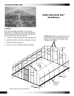
Страница 6: ...nd Post Frame length may differ from actual frame Gothic Style Solar Star Greenhouse OVERVIEW This section describes assembling your Gothic Style Greenhouse For details please see section Assembling the Gothic Style Greenhouse Components See illustration below to identify main parts of greenhouse 1 Locate the required parts for each assembly procedure 2 Assemble the rafters and frame and square th...

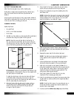
Страница 7: ... 6 Repeat the same step for the last corner post NOTE The distance measured diagonally between corner posts must be equal for the building to be square 7 Check all dimensions and adjust if needed before driving the remaining posts to the required height 8 After all corner posts are accurately installed tie a string line between the tops of the corner ground posts on the same side of the shelter Th...

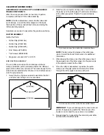
Страница 8: ...onto the ground posts 1 Select the five 5 pipes needed to assemble the first end rafter and arrange on a level surface 2 Slide four 4 end purlin clamps two on each side of the peak over the rafter pipes Position all end clamps at the rafter pipe joints Position the end clamps as shown 18G16A 166S075 18G16B NOTE Position all purlin clamps at the rafter pipe joints Consult the Quick Start section fo...

Страница 9: ...rlins ensures that an accurate spacing of the rafter assemblies is achieved and maintained during assembly Gather the Parts Pipe 1 315 x 75 swaged 131S075 Pipe 1 315 x XX plain 131P0XX Marker and tape measure NOTE The purlins are part of the assembled frame and run perpendicular to the rafter assemblies Each purlin consists of 1 315 x 75 131S075 swaged pipes number is determined by shelter length ...

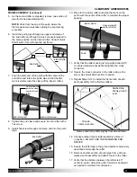
Страница 10: ...nector 102548 5 16 x 2 1 2 machine bolts and 5 16 nuts Lifts ladders and assistants Rope or cable 1 Carefully stand the first end rafter slide a band clamp onto each rafter leg and place the leg pipes in the first set of ground posts Brace the rafter in place to keep it straight Depending on the frame size a lift and additional assistants may be needed Consult Quick Start section for details Rafte...

Страница 11: ...e rafter to maintain the proper spacing Interior Rafter Align mark with center of rafter Purlin 11 Verify that the rafter spacing is forty eight inches 48 on center adjust as needed and tighten the cross connector 12 Secure the cross connector to the rafter using a Tek screw See Quick Start section if needed 13 Repeat Steps 6 12 to install the first section of each purlin assembly for the first tw...

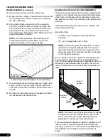
Страница 12: ...tached at ground level along both sides of the frame It helps keep the ground posts in place and also prevents the frame from working into the ground when anchored Attach the baseboards to the frame on the outside of the ground posts at this time Gather the Parts Treated or recycled plastic lumber supplied by customer 1 4 x 4 Carriage Bolts and 1 4 Nuts NOTE The following procedure describes one w...

Страница 13: ...or providing a baseboard for this frame If no baseboard is present attach the strut to the ground post using a Tek screw or other customer supplied fasteners 4 Repeat the above steps to attach the remaining side struts to the shelter 5 After securing the struts verify that all clamps are secured with a Tek screw to the rafters 6 Verify that each pipe splice purlin and rafter is secured with a Tek ...

Страница 14: ...e to install the additional horizontal framing for accessories Consult the diagrams in the Quick Start section showing the polycarbonate panel locations and the locations of the aluminum trim and profile before repositioning any end wall vertical DO NOT REPOSITION THE END WALL VERTICALS USED AT THE SEAM OF TWO 2 POLYCARBONATE PANELS Always consult the installation guides that shipped with the acce...

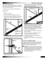
Страница 15: ...e between the top of the base tube and band clamp Step 7 to determine the length of the first door jamb NOTE If the measured length is longer than 99 an additional section of square tubing is required see Step 10 If the distance is 99 or shorter skip to Step 11 10 Choose one 1 square tube 102897 insert the swaged end of the long tube into the plain end of another tube and tap with a hammer to prop...

Страница 16: ...or the width of the rough door opening 20 Using two angle brackets attach the header tube to the end wall assembly between the door jambs as shown below 21 Verify that both door jambs are plumb and recheck the width of the door opening at the top and bottom Adjust if needed NOTE Do not secure the door to the door jambs at this time 22 Use the end frame diagram to determine the number of remaining ...

Страница 17: ... member 26 Choose a square to round tube connect bracket and attach the bracket to one end of the vertical frame member Use a 5 16 drill bit to drill a hole through the tube and attach the bracket to the tube using a nut and carriage bolt 27 With the square to round tube connect bracket attached to the top of the frame member place a square tube fitting on the bottom of the frame member Center Mar...

Страница 18: ... required height determined by the installation instructions included with that accessory using QH1330 brackets Dashed lines show where additional frame tubes are installed If you are not installing any accessories the accessory framing is not needed INSTALL THE END WALL FRAME continued TAPE SHARP EDGES AND CONNECTORS After the frame is assembled check the frame for sharp edges that could damage t...

Страница 19: ...emain intact and in direct sunlight will make the film difficult if not impossible to remove During preparation rest the edges of the panels on cardboard or other material to protect them from dirt and damage Seal the bottom edge of the panels with white vent tape Consult the polycarbonate panels Quick Start section for the location and lengths of each panel The diagrams are located at the back of...

Страница 20: ... a guide ATTENTION U channel profile is installed along the edges of the panels shown in the diagram below Profile installed here NOTE DO NOT damage the part of the polycarbonate panel removed during the cutting of the panel That portion is used to cover the small area above the door Always remove the protective film and mark and install the UV protected side to the outside of the greenhouse 3 App...

Страница 21: ...annel used to connect two separate panels 8 After cutting the panel to the proper width for above the door measure and cut two sections of H channel to the correct length H channel is used to join two separate panels NOTE The panel is cut to the proper height after it is attached to the end wall frame The H channel must be cut to a length that will allow for the installation of the final piece of ...

Страница 22: ...already done 14 Place the panel in position with its UV protected surface to the outside and attach the panel to the end wall framing as previously described End Cap H channel Trimmed polycarbonate panel above the door 10 With the H channel in place on the small panel and flush with the bottom of the panel measure the distance between the edges of the H channel at the bottom of the panel and cut a...

Страница 23: ...the closer the notches Install profile here ATTENTION The U channel profile for the top edge of all panels dashed line below is installed last and after all profile is installed along the edges and between each panel as shown on the end panel diagrams b The distance between the notches is determined by the degree of the bend required to fit the rafter c Bend the U channel profile at the notches be...

Страница 24: ...onsult the diagram below for clarification 2 Attach one section of the poly latch U channel to the side of the frame using Tek screws Attach U channel flush with the outside edge of the end wall panels Ribbon Board U channel Ribbon Board Rafter U channel must remain below the curve of the rafter NOTE Ribbon board and baseboard recommended shown in the diagram above are not included and are supplie...

Страница 25: ... near the edge of the material and below where the cover will be secured to the U channel 3 After tying the ropes to the main cover throw the ropes over the top of the greenhouse and pull the covers into place Use ropes to pull cover over the greenhouse and onto the frame ADDITIONAL ASSISTANCE IS REQUIRED 4 Center cover side to side and end to end Consult the Spec Sheets for cover identification T...

Страница 26: ... Move to the other end of the building and repeat the steps to secure the main cover in the U channel 10 After the cover is stretched end to end and secured using the spring and U channel move to one side of the greenhouse and repeat the steps to anchor the cover film to the first side NOTE Begin at one end of the U channel and work toward the other Another option is to begin at the middle of each...

Страница 27: ...rame NOTE The number of pipes used in the roll up conduit assembly varies with the length of the greenhouse Roll up conduit assemblies consist of multiple sections of swaged 1 315 pipe at 75 in length part 131S075 and one 1 additional plain 1 315 pipe at a shorter length part 131P0XX determined by the greenhouse where XX represents the remaining length required to complete the roll up conduit asse...

Страница 28: ...e conduit with Tek screws and fabric clips evenly spaced along the conduit 4 Continue to roll the conduit until the excess cover material is wound around the conduit 5 Repeat these steps for the other side of the shelter 6 With the excess cover material rolled up on the conduit assemblies continue with the Twist of the Wrist Assembly procedure TWIST OF THE WRIST ASSEMBLY Gather the parts Aluminum ...

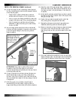
Страница 29: ...acket and attach the bearings as needed In some instances the bearings may come already attached Assemble as follows NOTE Single bearings are attached to the sides of the bracket and double bearings to the middle portion of the bracket Use 1 4 hex bolts and locknuts as needed Install a flat washer on both sides of each bearing to insure proper operation of bearings and the assembly 7 Install the l...

Страница 30: ...he same side of the mounting bracket 14 Finish rolling the cover conduit in a clockwise motion up to the Twist of the Wrist assembly INSTALL ANTI BILLOW ROPES Gather the Parts Eyebolts Anti Billow rope Nut and washers Anti billow ropes secure the roll up sides when they are in the down position Complete the following steps to install the ropes Repeat the steps for the remaining side TO PREVENT DAM...

Страница 31: ...o not have any tested loading criteria ATTENTION If no wood baseboard is present as required additional steps must be take to anchor the lower portion of the anti billow ropes 3 Move up the same end rafter and install the second eyebolt through the poly latch U channel and rafter leg NOTE If the poly latch U channel was attached to a ribbon board as suggested the eyebolt can be mounted through the...

Страница 32: ...SES 32 Revision date 10 03 14 QUICK START GUIDE 18 Gothic Style Greenhouse Frame shown may differ in length from actual frame Ground Level Height 18 0 9 6 15 16 Width 3 11 Sidewall Height FRONT Grid Represents 12 Squares ...

Страница 33: ...urlin Connection Notes Purlin connected to end rafter using 102856 clamp Purlin connected to mid rafters using 102548 connector Purlin connection See Connection Note Purlin connection See Connection Note Purlin connection See Connection Note 102675 1 90 Ground Post 102675 1 90 Ground Post Ground Level ...

Страница 34: ...ENHOUSES 34 Revision date 10 03 14 SIDE PROFILE 104848 131S075 131S075 131S075 Purlin Run 131P0255 4 0 on center Rafter Spacing 20 0 Length center to center Customer Supplied Baseboard Customer Supplied Ribbon Board ...

Страница 35: ...GREENHOUSES Revision date 10 03 14 SIDE PROFILE 104849 131S075 131S075 131S075 Purlin Run 131P0735 4 0 on center Rafter Spacing 24 0 Length center to center Customer Supplied Baseboard Customer Supplied Ribbon Board ...

Страница 36: ...USES 36 Revision date 10 03 14 SIDE PROFILE 104850 28 0 Length center to center 131S075 131S075 131S075 Purlin Run 131S075 131P0495 4 0 on center Rafter Spacing Customer Supplied Baseboard Customer Supplied Ribbon Board ...

Страница 37: ...SES Revision date 10 03 14 32 0 Length 131S075 131S075 131S075 Purlin Run 131S075 131S075 131P0255 center to center 4 0 on center Rafter Spacing SIDE PROFILE 104851 Customer Supplied Baseboard Customer Supplied Ribbon Board ...

Страница 38: ... 38 Revision date 10 03 14 36 0 Length 131S075 131S075 131S075 Purlin Run 131S075 131S075 131P0735 center to center 4 0 on center Rafter Spacing Customer Supplied Baseboard Customer Supplied Ribbon Board SIDE PROFILE 104852 ...

Страница 39: ...S Revision date 10 03 14 CONNECTIONS Endwall Baserail Connection View 1 Rafter Base Rail Connection View 2 Rafter Endwall Connection View 3 Purlin End Rafter Connection View 4 Purlin Mid Rafter Connection View 5 Ground Level ...

Страница 40: ... 4 Purlin End Rafter Connection View 2 Rafter Base Rail Connection View 5 Purlin Mid Rafter Connection View 3 Rafter Endwall Connection QH1402 1 66 Band Clamp Endwall Rafter 104074 Sq Rnd Tube Bracket Endwall Rafter Baserail 104624 1 Way Connector Purlin Rafter 102548 1 66 Cross Connector 102856 1 66 End Clamp Rafter Purlin ...

Страница 41: ...ng are full length or cut form 1 1 2 x 1 1 2 square tubing 102897 Non Critical verticals do not have specific placement in end wall framing They are included for polycarbonate support and framing of greenhouse accessories For the framing of greenhouse accessories check for rough opening and space verticals accordingly Do not change the position of the verical supporst as marked with on center meas...

Страница 42: ... placement in end wall framing They are included for polycarbonate support and framing of greenhouse accessories For the framing of greenhouse accessories check for rough opening and space verticals accordingly Do not change the position of the verical supporst as marked with on center measurements These must remain as shown to attach the polycarbonate panels on center 18 1 4 on center 18 1 4 NOTE...

Страница 43: ...GREENHOUSES Revision date 10 03 14 POLYCARBONATE PANELS FRONT VIEW 18 1 4 on center 18 1 4 on center Ground Level NOTE Install white vent tape on the bottoms of the polycarbonate panels Cut from one 6 x 10 panel A B ...

Страница 44: ...CLEARSPAN GREENHOUSES 44 Revision date 10 03 14 POLYCARBONATE PANELS BACK VIEW Ground Level NOTE Install white vent tape on the bottoms of the polycarbonate panels ...

Страница 45: ...45 CLEARSPAN GREENHOUSES Revision date 10 03 14 Page reserved for customer notes ...

Отзывы: