background image

CLEARSPAN

 VALUE LINE

10

Revision date: 03.10.08

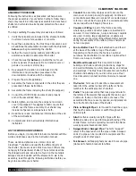
With the purlin in position, tighten the clamp at the peak 
of the end rafter as shown below.

6.

FRAME ASSEMBLY (CONTINUED)

Align the pre-marked location on the purlin with the 
center of the inside rafter to achieve the proper rafter 
spacing and tighten the cross-connector. 

7.

NOTE:

 If needed, use a hammer to tap the cross-

connector and the purlin to the center mark. 

Verify that both rafters are plumb and that the 5' on-
center rafter spacing is maintained after both clamps 
are tightened. 

You may need to loosen the clamp on the end rafter 
and adjust the purlin if the second rafter is plumb but 
the mark on the purlin does not align with the center of 
the mid rafter.  

DO NOT ALLOW THE PURLIN TO EXTEND BEYOND 
THE OUTSIDE EDGE OF THE END RAFTER.

After tightening the cross-connector, install a Tek screw 
(#FA4482B) through the cross-connector and into the 
purlin.

Position the Tek screw so that it also secures the 

joint of the purlin pipe

.

8.

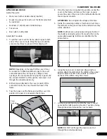
The first purlin and the first two rafters should appear 
as shown below.

Reposition the rafter legs of the first interior rafter (if 
needed) to achieve and maintain the 5' on-center rafter 
spacing and the 22' center-to-center width.

Select the first section of the 

second pre-marked purlin

and install it as you did the top/center purlin. 

NOTE:

 Slide the purlin through the cross-connector 

as shown below at the joint of the curved leg pipe and 
long straight pipe. 

9.

10.

102857

End Clamp

End Rafter

Top purlin

End Rafter

First section of purlin

Interior Rafter

22'

center-to-center

5'

on-center

Tek Screw

Содержание 105595

Страница 1: ...le Side Profile Connection Call Out Connection Details Rafter Pipe Details Cover and End Panel Details New or Special Components B O M Information CONTENT GUIDE 105595 K End Framing Width Center Center Sidewall Height Rafter Spacing Length Center Center Rafter Tubing Cover Conduit Tubing Height Ground Peak Purlin Tubing of Runs Cover Info End Wall Door End Wall Tubing End Panel Info Shelter Inform...

Страница 2: ... shelter sides near bottom Sercured using a tek screw Placed on end rafters and every other mid rafter NOTE All purlins are connected to the end rafter using end purlin connectors Purlins are connected to mid rafters using cross connectors 131P0455 D C B A A B C D 1 2 3 4 5 6 7 8 8 7 6 5 4 3 2 1 B1 1 0 Engineering Approval Manger Approval Design Approval Engineering Services Products Co Shelter De...

Страница 3: ...after Spacing 20 0 Length D C B A A B C D 1 2 3 4 5 6 7 8 8 7 6 5 4 3 2 1 C1 1 0 Drawn By Creation Date Last Revision Date 1 4 2006 1 4 2006 CJO 105595 22 W x 11 H x 20 L 2 CAR GARAGE Shelter Sku Number Shelter Dimensions Shelter Description Engineering Services Products Co Design Approval Manger Approval Engineering Approval SIDE PROFILE ...

Страница 4: ...er Connection E1 1 0 View 2 D C B A B C D 1 2 3 4 5 6 7 8 8 7 6 5 4 3 2 1 A D1 1 0 Engineering Approval Manger Approval Design Approval Engineering Services Products Co 2 CAR GARAGE 22 W x 11 H x 20 L 105595 Shelter Description Shelter Dimensions Shelter Sku Number Last Revision Date Creation Date Drawn By 1 4 2006 1 4 2006 CJO CONNECTIONS ...

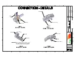
Страница 5: ...ption Shelter Dimensions Engineering Services Products Co Design Approval Manger Approval Engineering Approval E1 1 0 CONNECTION DETAILS VIEW 1 RATCHET RAFTER VIEW 2 PURLIN MID RAFTER Mid Rafter Purlin Cross Connector VIEW 3 BASE RAIL RAFTER IMPORTANT Base rail is installed with the end panel Rail is placed partially in panel pocket See instructions for panel installation Purlin End Clamp Purlin E...

Страница 6: ... 2 3 4 5 6 7 8 8 7 6 5 4 3 2 1 CJO 1 4 2006 1 4 2006 Drawn By Creation Date Last Revision Date 2 CAR GARAGE 22 W x 11 H x 20 L 105595 Shelter Sku Number Shelter Dimensions Shelter Description Engineering Services Products Co Design Approval Manger Approval Engineering Approval G1 1 0 RAFTER PIPE DETAILS DIA GA DIA GA PRE BEND PRE BEND TYPE TYPE PT TO PT PT TO PT BEND LCTN BEND LCTN DEGREE DEGREE D...

Страница 7: ...B A A B C D 1 2 3 4 5 6 7 8 8 7 6 5 4 3 2 1 Drawn By Creation Date Last Revision Date 1 4 2006 1 4 2006 CJO 2 CAR GARAGE 22 W x 11 H x 20 L 105595 Shelter Description Shelter Dimensions Shelter Sku Number Engineering Services Products Co Design Approval Manger Approval Engineering Approval H1 1 0 MAIN COVER DETAILS ...

Страница 8: ...ers Back end panel is plain 1 3 6 112 09 1 3 6 D C B A A B C D 1 2 3 4 5 6 7 8 8 7 6 5 4 3 2 1 1 4 2006 1 4 2006 CJO Drawn By Last Revision Date Creation Date 2 CAR GARAGE 22 W x 11 H x 20 L 105595 Shelter Sku Number Shelter Description Shelter Dimensions Engineering Services Products Co Design Approval Manger Approval Engineering Approval H2 1 0 FRONT END PANEL DETAILS ...

Страница 9: ... and during construction are answered within the instructions and these pages Cover and End Panel Details Over the top 7 5oz Silver White Fabric no stretch hem End Panels 7 5oz Silver White Fabric Front 3 Zipper Door Back Solid No Zippers Reference the instruction manual for cover and end panel installation D C B A A B C D 1 2 3 4 5 6 7 8 8 7 6 5 4 3 2 1 Drawn By Last Revision Date Creation Date 1...

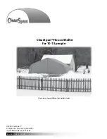
Страница 10: ...ision date 03 10 08 ClearSpan House Shelter for 10 15 people 2008 ClearSpan All Rights Reserved Reproduction is prohibited without permission STK DIMENSIONS 105595 22 W x 11 H x 20 L Photo may show a different but similar model ...

Страница 11: ...facturer s warranty and may cause serious injury and damage LOCATION Choosing the proper location is an important step before you begin to assemble the structure The following suggestions and precautions will help you determine whether your selected location is the best location Never erect the structure under power lines Identify whether underground cables and pipes are present before preparing t...

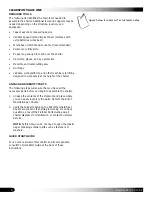
Страница 12: ...lers and the straight ends of other pipes Tek Screw A self tapping fastener used to secure pipe joints and to fasten brackets to rafters ASSEMBLY PROCEDURE Following the instructions as presented will help ensure the proper assembly of your shelter Failing to follow these steps may result in an improperly assembled and anchored shelter and will void all warranty and protection the owner is entitle...

Страница 13: ...at the height of the shelter UNPACK AND IDENTIFY PARTS The following steps will ensure that you have all the necessary parts before you begin to assemble the shelter Unpack the contents of the shipment and place where you can easily inventory the parts Refer to the Bill of Materials Spec Sheets Verify that all parts listed on the Bill of Materials Spec Sheets are present If anything is missing or ...

Страница 14: ... show you how they are used Not all parts are shown Zippered End Panel Plain End Panel CC6214 Fabric Clips FA4482B Tek Screw 102857 End Clamp 102547 Cross Connector QH1061 Ratchet 103620b Plain End Strap Swaged Plain Swaged and Plain Rafter Sections not all pieces are shown QH1404 Band Clamp QH1330 Angle Bracket 104074 Bracket ...

Страница 15: ...r assembling your ClearSpan Housing Shelter For details please see section Assembling the ClearSpan Housing Shelter Components See illustration below to identify main parts of shelter Locate the required parts for each assembly procedure Assemble the rafters and frame Square and anchor the frame Prepare and install end panels Attach ratchets and install main cover 1 2 3 4 5 ...

Страница 16: ...equired to assemble the shelter RAFTER ASSEMBLY Gather the parts Rafter pipe 22G1903 Rafter pipe 22G1901 Pipe 1 90 x 99 swaged End clamps 102857 and Tek screws Nut setter 3 8 x 2 9 16 magnetic Rafter Assembly Procedure Each rafter assembly consists of five 5 rafter sections 1 curved center pipe for the top or peak 2 curved leg pipes and 2 straight pipes that connect the legs to the top center pipe...

Страница 17: ... accurate spacing of the rafter assemblies is achieved Required Pipe 1 315 x 75 swaged pipe 131S075 1 315 x 25 5 plain pipe 131P0255 NOTE Purlins are part of the assembled frame and run perpendicular to the rafter assemblies There are seven 7 purlins that run perpendicular to the rafter assemblies Each purlins consists of three 3 1 315 x 75 131S075 swaged pipes and one 1 1 315 x 25 5 131P0255 plai...

Страница 18: ...acing Verify that the rafter is plumb straight 2 NOTE In the previous photo ropes identified by white lines for clarity were used to temporarily anchor the rafter in place For this first end rafter all temporary bracing must remain in place until other rafters are set in place and attached to the first rafter and to each other Set the second rafter first inside rafter in place and secure it to the...

Страница 19: ...enter of the mid rafter DO NOT ALLOW THE PURLIN TO EXTEND BEYOND THE OUTSIDE EDGE OF THE END RAFTER After tightening the cross connector install a Tek screw FA4482B through the cross connector and into the purlin Position the Tek screw so that it also secures the joint of the purlin pipe 8 The first purlin and the first two rafters should appear as shown below Reposition the rafter legs of the fir...

Страница 20: ...See the arrow in the following diagram NOTE Do not remove the temporary bracing until additional rafters are in place 14 To this point the assembled frame includes two rafters and three purlins as shown After attaching the first section of the third purlin to the rafters move up the rafter assembly and place a cross connector over the mid rafter pipe and install the first sections of the next two ...

Страница 21: ...e the remaining end rafter This end rafter includes the end clamps attached during the rafter assembly procedures and is identical to the first end rafter set in place Set the end rafter in place and align the purlins with the end clamps previously attached to the rafter Begin with the top end clamp and ensure that approximately half an inch of the purlin extends through the pipe strap and tighten...

Страница 22: ...uring diagonally corner to corner and make sure that the two measurements are equal 1 2 3 Examine the framework and remove any sharp edges from the frame or reposition clamps and screws so they do not come in contact with the end panels or the main cover 4 Tape all rafter splices with duct tape to protect the main cover when it is installed Verify that all pipe splices are secured using Tek screws...

Страница 23: ...end panels unfold each panel at the base of the assembled frame where they will be installed with the inside surface facing up 1 On the zippered end panel insert the end conduit through the two side panels of the end panel as shown below and not through the door sections 2 End Conduit through Side Panel End Conduit through Side Panel ATTACH END CONDUIT ASSEMBLIES Using two 2 QH1330 angled brackets...

Страница 24: ...the remaining fabric clips for the first panel and secure the panel to the back of the rafter using the clips Evenly space the clips and work along the rafter NOTE Secure each fabric clip to the end rafter using a Tek screw Position the clip and the Tek screw in a location that will not contact the main cover when it is installed Actual number of clips may differ from what is shown in the diagram ...

Страница 25: ...arrive at the correct length 3 Locate all sections of pipe needed to assemble the cover conduit Insert the swaged end of each pipe into the plain end of another pipe until the conduit is assembled Secure each pipe joint with a Tek screw a b c NOTE Use duct tape to tape the Tek screws to prevent damage to main cover Cover conduits are inserted into the pockets sealed into the main cover The conduit...

Страница 26: ...rame and pull the cover into position One person is required at each rope 2 3 Once the main cover is pulled into position center the cover on the frame and remove the ropes Loosely secure the ends of the cover to the ratchets attached to the end panel conduits ATTENTION Do not tighten the straps at this time Divide the remaining number of ratchets in half Place the ratchets on the ground next to t...

Страница 27: ...nance of your shelter is important Check the following items periodically to properly maintain your shelter Regularly check the main cover and panels if equipped to see that these remain tight and in proper repair Check connections and all fasteners to verify that they remain tight Do not climb or stand on the shelter at anytime Remove debris and objects that may accumulate on the shelter Use tool...

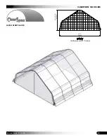
Страница 28: ...19 CLEARSPAN VALUE LINE Revision date 03 10 08 QUICK START GUIDE 22 Wide House Style Two Car Garage Grid Represents 12 Squares FRONT 22 0 Width 10 11 3 16 Height ...

Страница 29: ...9 Purlin Connection 10 from ground Purlin Connection 5 from ground Purlin Connection center of shelter Purlin Connection middle of straight rafter NOTE All purlins are connected to the end rafter using end purlin connectors Purlins are connected to mid rafters using cross connectors 131P0455 Purlin Connection 10 from ground ...

Страница 30: ...N VALUE LINE Revision date 03 10 08 SIDE PROFILE 105595 Purlin Run Cover Conduit 131S075 131S075 131S075 131P0255 atchets are attached on the sides of the rafters la led ith an R R R R R 5 0 after pacing 0 0 ength ...

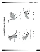
Страница 31: ...CLEARSPAN VALUE LINE 22 Revision date 03 10 08 CONNECTIONS Ratchet Rafter Connection iew ase Rail Rafter Connection iew Purlin nd Rafter Connection iew Purlin id Rafter Connection iew 2 ...

Страница 32: ...R R 0 ase Rail Rafter Leg 1 R R R 2 P R R R id Rafter Purlin Cross Connector 3 S R R R P R ase rail is installed with the end panel Rail is placed partiall in panel poc et See instructions for panel installation Purlin nd Cla p Purlin nd Rafter Rafter Leg Ratchet e Screw ...

Отзывы: