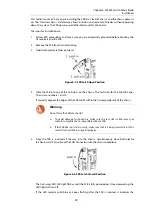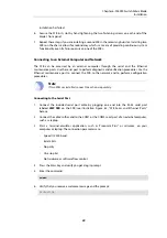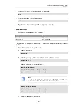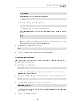
Connect AC Power Cords
To connect the AC power cords, the steps are:
•
Follow the safety precautions described previously.
•
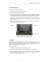
Stand facing the rear of the power enclosure.
•
Plug the C21 connector end of one of the AC power cords into the C22 connector on the far
right of the power enclosure. This is the connector for the power supply that was installed in
the front left slot of the enclosure (see
Installing Power Supplies
above for more information).
•
Plug the second AC power cord into the C22 connector on the mid-right of the power
enclosure. This is the connector for the power supply that was installed in the front middle
slot of the enclosure.
•
Plug the wall connector ends of the AC power cords into the AC outlets on the wall. Power is
immediately provided to the power enclosure.
Figure 8.5. Chassis on Power Rack - Rear View
Powering Up
In the following steps, a loud alarm may sound if an alarm condition occurs and the chassis has
the alarm panel installed. Be prepared to insert the end of a pen or a paperclip into the pinhole
labeled with the "alarm off" graphic (a bell with line through it) on the front panel to press the
button. This acknowledges and silences the alarm.
To power up the chassis:
•
Switch the PEM circuit breakers to the ON position, one at a time.
•
Verify the power LEDs on the PEMs and any installed front blades are all lit solid green.
•
Allow any automatic boot-up actions to occur on the chassis and then verify the hot-swap
LEDs stop blinking on all blades. If any hot-swap LED continues to blink for more than two
minutes, verify the blade is properly latched.
Chapter 8: The Power Enclosure
33

