Optimus DA-4PM/0F2, Operating Instructions Manual
The Optimus DA-4PM/0F2 Operating Instructions Manual is a comprehensive user guide that ensures hassle-free operation of your Optimus DA-4PM/0F2 device. This manual is an essential resource, providing step-by-step instructions and informative details. Download the user manual for free from manualshive.com to unlock the full potential of your Optimus DA-4PM/0F2.
Share
Download


Reviews:
No comments
Related manuals for DA-4PM/0F2

SC836 Series
Brand: Supermicro Pages: 146

HWC12P Series
Brand: magicpak Pages: 2

LC7.2E
Brand: Philips Pages: 111

LC4.41A AA
Brand: Philips Pages: 87

TE1.1E
Brand: Philips Pages: 46

TES1.0E LA
Brand: Philips Pages: 76

TPN15.2E LA
Brand: Philips Pages: 71

VES1.1E
Brand: Philips Pages: 79

LC8.1E
Brand: Philips Pages: 71

TPM16.1E LA
Brand: Philips Pages: 69

LC4.5E
Brand: Philips Pages: 80
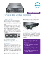
PowerEdge C5000
Brand: Dell Pages: 2

IPC-3026
Brand: Advantech Pages: 30

HPC-7484
Brand: Advantech Pages: 32

SC829BTQ-R920WB
Brand: Supermicro Pages: 88

SC846TQ-R900B
Brand: Supermicro Pages: 97

SC825M Series
Brand: Supermicro Pages: 88

iMcV/18
Brand: IMC Networks Pages: 2


