background image

14

Parts & Service: 020 8988 7400 / E-mail: [email protected] or [email protected]

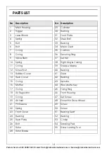
PARTS LIST

No

Description

No

Description

1

Main Housing

29

Cylinder

2

Trigger

30

Bushing

3

Lever Block

31

Front Plate

4

Spring

32

Steel Ball

5

Bolt

33

Bearing

6

Bolt

34

Major Gear

7

O-ring

35

Cushion

8

O-ring

36

Securing Ring

9

Valve Stem

37

Set Nut

10

Spring

38

Right Angle Casing

11

O-ring

39

Grease Nipple

12

Screw Nut

40

Bearing

13

Rubber Cover

41

Gear

14

Rear Cover

42

Bearing

15

O-ring

43

Spindle

16

Muffler

44

Woodruffe Key

17

O-ring

45

Fixing Ring

18

Air Regulator

46

Front Housing

19

O-ring

47

Set Screw

20

Air Inlet

48

Eccentric Drive Wheel

21

Pin Sleeve

49

Screw

22

Spring

50

Screw

23

Front Cover

51

Bearing Seat

24

Bearing

52

Bearing

25

Rear Plate

53

Circlip

26

Bolt

54

Sanding Pad

27

Rotor

55

Drive Locking Tool

28

Rotor Blade

Содержание X-Pro CAT168

Страница 1: ...OPERATING MAINTENANCE INSTRUCTIONS ORIGINAL INSTRUCTIONS GC0417 RIGHT ANGLE SANDER MODEL NO CAT168 PART NO 3120182...

Страница 2: ...ese instruction in a safe place for future reference SPECIFICATION Please note that the details and specifications contained herein are correct at the time of going to print However CLARKE Internation...

Страница 3: ...footing and balance at all times 4 Never use oxygen CO2 combustible gasses or any bottled gas as a source of power for an air tool This product should only be used with a suitably rated compressed ai...

Страница 4: ...ibrates with use Vibration may be harmful to your hands or arms Stop using the tool if discomfort a tingling feeling or pain occurs Seek medical advice before resuming use SANDER SPECIFIC SAFETY RULES...

Страница 5: ...y long air hose is required over 8 metres the line pressure or the hose inside diameter may need to be increased The air hose must be rated at least 150 of the maximum operating pressure of the air to...

Страница 6: ...air pressure to this tool does not exceed 6 2 bar 90 psi at the tool when running Higher pressures and unclean air will shorten the life of the tool due to faster wear and is a possible safety hazard...

Страница 7: ...an be removed by unscrewing anticlockwise FITTING REMOVING THE SANDING DISC 1 Fit the backing disc to the sander by locking the moving drive spindle with the key supplied and screwing the disc tightly...

Страница 8: ...er preferably via a quick release coupling not supplied 7 Ensure the trigger is NOT depressed when connecting the air line Your sander is now ready for use You can fit a whip hose with a quick fit cou...

Страница 9: ...he direction of the exhaust air leaving the tool can be adjusted by rotating the exhaust deflector 1 Twist the exhaust deflector sleeve to direct the air as required to deflect air away from the workp...

Страница 10: ...ng a few drops into the air inlet immediately before use This should be carried out regardless of whether or not an in line lubricator is used 3 Keep the sander clean and free from debris CLEANING OVE...

Страница 11: ...ch of children Avoid storing in a damp environment ABRASIVE DISCS Replacement hook and eye backed abrasive discs 2 50mm dia are available from your CLARKE dealer GUARANTEE This product is guaranteed a...

Страница 12: ...the force applied to the sander 2 Return to Clarke dealer for repair 3 Drip air tool lubricating oil into air inlet Allow oil to soak moving parts before using Tool runs slowly Air flows weakly from e...

Страница 13: ...13 Parts Service 020 8988 7400 E mail Parts clarkeinternational com or Service clarkeinternational com PARTS DIAGRAM...

Страница 14: ...ng Ring 9 Valve Stem 37 Set Nut 10 Spring 38 Right Angle Casing 11 O ring 39 Grease Nipple 12 Screw Nut 40 Bearing 13 Rubber Cover 41 Gear 14 Rear Cover 42 Bearing 15 O ring 43 Spindle 16 Muffler 44 W...

Страница 15: ...15 Parts Service 020 8988 7400 E mail Parts clarkeinternational com or Service clarkeinternational com DECLARATION OF CONFORMITY...

Страница 16: ......

Отзывы: