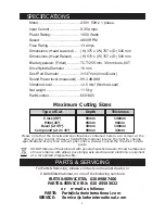
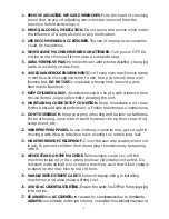
Clarke woodworker CMS10 6501305 Скачать руководство пользователя страница 4

SAFETY PRECAUTIONS

GENERAL SAFETY RULES FOR OPERATING  MACHINERY

WARNING:

As with all machinery, there are certain hazards involved with their

operation and use. Exercising respect and caution will considerably

lessen the risk of personal injury. However, if normal safety precautions

are overlooked or ignored, personal injury to the operator or damage to

property, may result.

1.

READ 

and 

BECOME FAMILIAR

 with the entire operating manual. Learn

the machines’ applications and limitations as well as the specific
potential hazards peculiar to it.

2.

EARTH ALL MACHINES.

 If the machine  is equipped with three-pin plug,

it should be plugged into a three-pin electrical socket. Never remove
the earth pin.

3.

ALWAYS 

ensure that 

ADEQUATE LIGHTING

 is available. A minimum

intensity of 300 lux should be provided. Ensure that lighting is placed
so that you will not be working in your own shadow.

4.

CHECK 

for 

DAMAGE

. Before using the machine, any damaged part,

such as a guard etc., should be checked to ensure that it will operate
properly, and perform its intended function. Check for alignment of
moving parts, breakage of parts, mountings, and any other condition
that may affect the machines’ operation. Any damage should be
properly repaired or the part replaced. If in doubt, DO NOT USE the
machine. Consult your local dealer.

5.

DISCONNECT 

the 

MACHINE 

from the power supply before servicing

and when changing accessories such as blades, etc.

6.

KEEP GUARDS 

in place and in working order.

7.

ALWAYS WEAR SAFETY GOGGLES,

 manufactured to the latest European

Safety Standards. Also use a face or dust mask if the cutting operation
is dusty. Everyday eyeglasses do not have impact resistant lenses, they
are NOT safety glasses.

8.

KEEP WORK AREA CLEAN.

 Cluttered areas and benches invite accidents.

9.

ALWAYS WEAR EAR PROTECTORS/DEFENDERS 

as this machine generates

considerable noise which can be in excess of 97dBA.

10.

DON’T FORCE

 the machine. It will do a better and safer job at the rate

for which it was designed.

4

Содержание woodworker CMS10 6501305

Страница 1: ...02 08 Part Number 6501305 Operating Maintenance Instructions 10 COMPOUND MITRE SAW 10 COMPOUND MITRE SAW Model CMS10...

Страница 2: ...pindle Diameter 16 mm Dust Port Diameter 31 37 mm Inner Outer Sound Power level measured 99 3 dBLWA Vibration Level 2 5 m s Normal Load Net weight 11 5 kg Part Number 6501305 Please note that the deta...

Страница 3: ...ase keep your receipt as proof of purchase This guarantee is invalid if the product is found to have been abused or tampered with in any way or not used for the purpose for which it was intended Fault...

Страница 4: ...DAMAGE Before using the machine any damaged part such as a guard etc should be checked to ensure that it will operate properly and perform its intended function Check for alignment of moving parts br...

Страница 5: ...N MACHINE IN TOP CONDITION Keep tools sharp and clean for the best and safest performance Follow maintenance instructions 21 DON T OVERREACH Keep your proper footing and balance at all times For best...

Страница 6: ...st all be in place and securely fastened when performing any operation 10 Use ONLY approved replacement saw blades Contact your local CLARKE dealer for advice The use of inferior blades may increase t...

Страница 7: ...d with a plug which is moulded onto the electric cable i e non rewirable please note 1 The plug must be thrown away if it is cut from the electric cable There is a danger of electric shock if it is su...

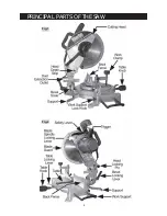
Страница 8: ...PRINCIPAL PARTS OF THE SAW 8 Fig 1 Fig 2...

Страница 9: ...ations on page 3 A dust extraction outlet is provided at the rear of the machine on to which the dust bag supplied is fitted If necessary hose from a vacuum cleaner may be attached to provide fast and...

Страница 10: ...ted to a workbench the rear support must be fitted see Figs 1 and 2 A single bolt secures the support to the rear of the base housing The Cutting Head is locked in its lower position for transit purpo...

Страница 11: ...treat the machine with indifference and NEVER be casual with your approach To switch off release the trigger whilst still maintaining full control of the head NEVER allow the head to spring upwards a...

Страница 12: ...g lever and swing the head to the side Lower the arm and bring your template up to the saw blade When satisfied that the edge of template and blade are parallel lock the head in position with locking...

Страница 13: ...ARKE dealer for advice 2 Changing the Saw Blade IMPORTANT Exercise extreme care when handling the saw blade The tips are extremely sharp and careless handling could result in severe personal injury 13...

Страница 14: ...e outer flange followed by the saw blade NOTE You should take this opportunity to thoroughly clean parts previously inaccessible By removing the collar it is possible to use blades with a 16mm bore 8...

Страница 15: ...just the head using the 90 adjuster screw shown in Fig 13 To do this slacken off the bevel locking lever then lower the arm and lock in place with the head locking knob Place a small square on the tab...

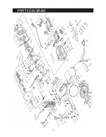
Страница 16: ...PARTS DIAGRAM 16...

Страница 17: ...1 GRCMS1045 46 Cable 1 GRCMS1046 47 Cable Armor 1 GRCMS1047 48 Rubber Washer 2 GRCMS1048 49 Cable Armor 1 GRCMS1049 50 Nut Wrench 1 GRCMS1050 51 Lengthening Nut 1 GRCMS1051 52 Armor 1 GRCMS1052 53 Sp...

Страница 18: ...18...

Страница 19: ...19...

Страница 20: ......

Отзывы: