background image

20

Parts & Service: 020 8988 7400 / E-mail: [email protected] or [email protected]
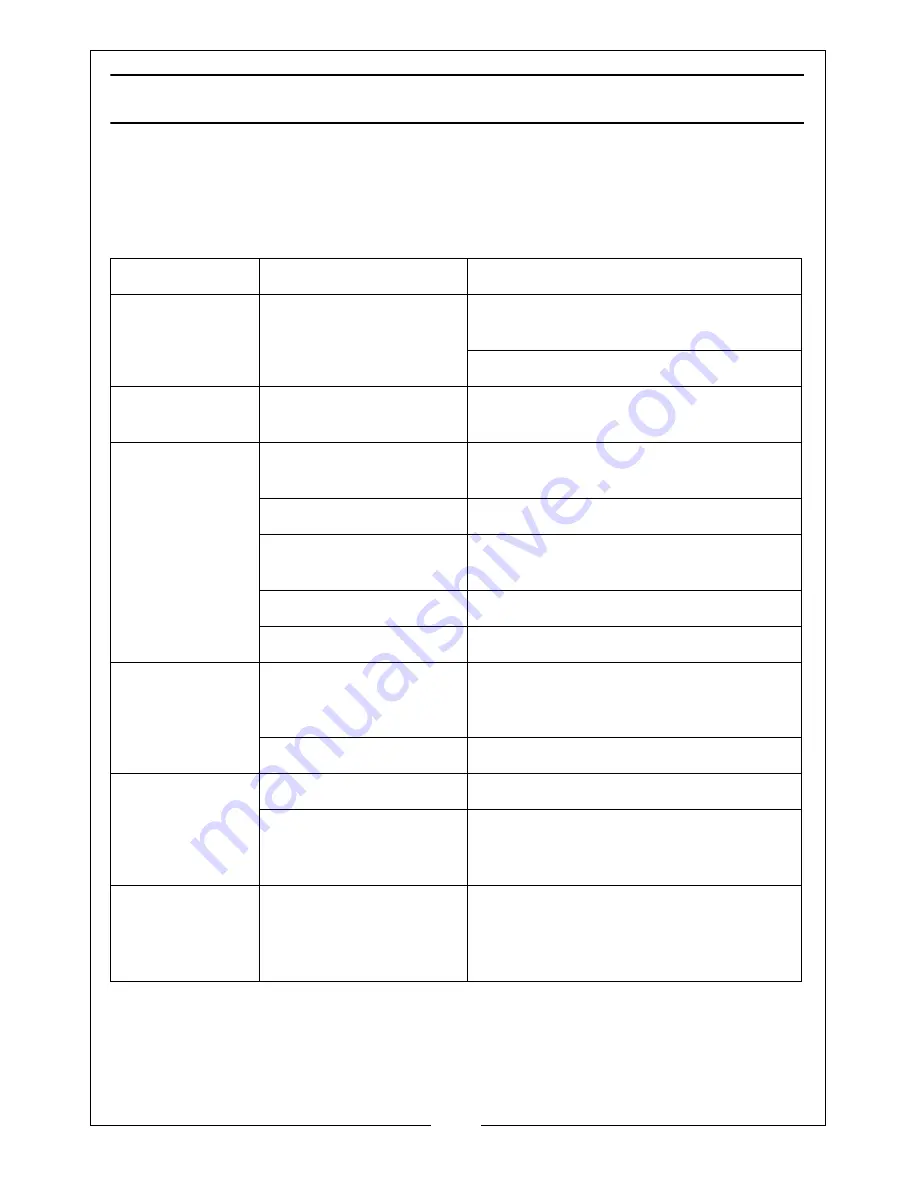
TROUBLESHOOTING

Your CLARKE MIG Welder has been designed to give long and trouble free 
service. If, however, having followed the instructions in this booklet carefully, 
you still encounter problems, the following points should help identify and 

resolve them.

PROBLEM

CAUSE

SOLUTION

No response from 
welder

Check fuses and mains 
lead

Replace fuses as necessary, If problem 
persists return welder to your local dealer

Check fuse size

Welder does not 
feed wire

Feed motor has malfunc-
tioned.

Return welder to your local dealer

Feed motor run-
ning but no wire 
being fed from 
welder tip

Insufficient Feed Roller 
pressure

Increase roller pressure

Burr on end of wire

Re-cut wire square with no burr

Liner blocked or dam-
aged

Clean with compressed air or replace 
liner.

Inferior wire

Use only good “clean” wire

Roller worn out

Replace roller

Wire welds itself 
to tip

Wire feed speed too low

Unscrew tip, cut wire and fit new tip
Increase wire speed before operating 
again

Wrong size tip

Fit correct size tip

Wire feeds into 
‘birds nest’ tan-
gle

Wire welded to tip

As above plus reduce feed roller pressure

Wire liner damaged pre-
venting smooth opera-
tion

Renew wire liner

Loose coils of 
wire tangle 
around wire drum 
inside machine

Locking knob too slack

Tighten Locking Knob slightly. Do not 
over-tighten

Содержание MIG102NG

Страница 1: ...WARNING Read these instructions before using the machine OPERATION MAINTENANCE INSTRUCTIONS LS0214 NO GAS MIG WELDER MODEL NO MIG102NG PART NO 6015600...

Страница 2: ...of purchase This guarantee is invalid if the product is found to have been abused or tampered with in any way or not used for the purpose for which it was intended Faulty goods should be returned to t...

Страница 3: ...ELD 7 ELECTRICAL CONNECTIONS 8 UNPACKING 9 Opening The Cover 9 OVERVIEW 10 THE CONTROL PANEL 11 PREPARATION FOR USE 12 Mounting The Welding Wire Spool 12 Setting The Drive Roller Size 12 Threading The...

Страница 4: ...is secured to bare metal adjacent to weld seam and when not in use is insulated for safety Keep all equipment well maintained The operator shall prevent any gas cylinders in the vicinity of the work...

Страница 5: ...protection filters Where there are pedestrians and traffic ensure a protective screen is used to avoid accidental arc glare Do not weld in the vicinity of children or animals and ensure no one is look...

Страница 6: ...a fire extinguisher handy Dry Powder C02 or BCF NOT Water NEVER remove any of the panels unless the machine is disconnected from the power supply AND never use the machine with any of the panels remo...

Страница 7: ...LD 1 Push the two halves of the shield together as shown making sure the hooks and pins on the side engage correctly 2 Place the handle into position and secure using the plastic nut provided 3 Workin...

Страница 8: ...d of safely as insertion into a mains socket could cause an electrical hazard The wire which is coloured Blue must be connected to the terminal which is marked N or coloured Black The wire which is co...

Страница 9: ...arth clamp attached 2 x 0 9 mm Torch Tips one installed in the torch 1 x Spool Of Flux Cored Wire 1 x Combination Wire Brush Hammer 1 x Split Welding Mask 1 x Instruction Manual OPENING THE COVER IMPO...

Страница 10: ...rvice 020 8988 7400 E mail Parts clarkeinternational com or Service clarkeinternational com OVERVIEW NO DESCRIPTION NO DESCRIPTION 1 Handle 4 Hammer Brush Tool 2 Control Panel 5 Torch 3 Earth Clamp 6...

Страница 11: ...tes the light will go out the power will be restored and welding can recommence 2 Power ON OFF switch When the power is ON the green switch will be illuminated When the welder is no longer required th...

Страница 12: ...it sits on the spring Do not release the tension on the wire as it will unravel causing feeding problems later The wire will feed off the spool anticlockwise from the bottom of the reel The spool must...

Страница 13: ...ace THREADING THE WIRE IMPORTANT Do not release the tension on the wire as it will unravel causing feeding problems later 1 Pull out the end of the wire from the spool taking care not to release the t...

Страница 14: ...nel to position 7 or 8 and squeeze the trigger on the torch body The wire will feed through the hose until it appears at the torch tip Ensuring the hose is free from kinks during this process will ass...

Страница 15: ...wire When using the welder outside you may need to erect a wind break OPERATING THE WELDER PREPARING THE WORKPIECE The area being welded should be perfectly clean Any coating plating or corrosion must...

Страница 16: ...re to start with too high a speed and back off slightly to avoid the possibility of the wire welding itself to the tip This is the reason position 6 is recommended for start up NOTE The Wire Feed cont...

Страница 17: ...ven period for a specified welding current Using the example shown which is an illustration of the data plate e g when welding at 35 amps the machine may be used for 6 minutes 60 in any 10 minute peri...

Страница 18: ...moving all dust deposits Torch Protect the torch hose assembly from mechanical wear Clean the liner from the machine forwards by using compressed air If the liner is blocked it must be replaced Contac...

Страница 19: ...ated maximum supply current 5 British Standards applied 17 Maximum effective supply current 6 Welding process 18 N A 7 This symbol indicates that the unit is suitable for carrying out welding operatio...

Страница 20: ...lder to your local dealer Feed motor run ning but no wire being fed from welder tip Insufficient Feed Roller pressure Increase roller pressure Burr on end of wire Re cut wire square with no burr Liner...

Страница 21: ...e on feed roller Caution Do not over tighten Wire dirty rusty damp or bent Re cut wire and ensure it is clean Liner partially blocked Clean with compressed air Poor quality welds Poor earth contact Ch...

Страница 22: ...i e 10 means 1 minutes operation followed by 9 minutes of rest The duty cycle must not be exceeded to to prevent the thermal cutout protection from activating Do not exceed the stated duty cycle for...

Страница 23: ...23 Parts Service 020 8988 7400 E mail Parts clarkeinternational com or Service clarkeinternational com DECLARATION OF CONFORMITY...

Страница 24: ......

Отзывы: