background image

10

Parts & Service: 020 8988 7400 / E-mail: [email protected] or [email protected]

THE WELDING SHIELD

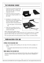
1. Push the two halves of the shield 

together as shown, making sure 
the hooks and pins on the side 
engage correctly.

2. Place the handle into position 

and secure using the plastic nut 
provided.

3. Working from the inside of the 

shield, insert the clear glass panel 
into the recess in the shield, 
followed by the dark glass panel.

• The clear glass must be inserted 

first.

4. Insert the two plastic screws to 

clamp the glass panels from the 
inside of the mask. 

When replacing the glass panels, 
only use parts supplied by Clarke International. The dark panel is a certified, 
specific optical class, and should not be exchanged for any other type.

The clear glass panel should be replaced when it becomes badly pitted.

PREPARATION FOR USE

FITTING THE WELDING ROD

1. Select the appropriate welding rod, and insert it into the welding rod 

holder.

• It should be approximately the same thickness as the metal being 

welded.

PREPARING THE WORKPIECE

The area being welded should be perfectly clean. Any coating, plating or 
corrosion must be removed, otherwise a good weld will be impossible to 
achieve.

Содержание EASIARC 200

Страница 1: ... Read these instructions before using the machine WARNING A suitable welding headsheild must be worn during use OPERATION MAINTENANCE INSTRUCTIONS LS0415 200 AMP ARC WELDER MODEL NO EASIARC 200 PART NO 6010980 ...

Страница 2: ...id if the product is found to have been abused or tampered with in any way or not used for the purpose for which it was intended Faulty goods should be returned to their place of purchase no product can be returned to us without prior permission This guarantee does not effect your statutory rights ENVIRONMENTAL PROTECTION Do not dispose of this product with general household waste All tools access...

Страница 3: ...cured to bare metal adjacent to weld seam and when not in use is insulated for safety Keep all equipment well maintained The operator shall prevent gas cylinders in the vicinity of the work piece from becoming part of the welding circuit FUMES GASES The welding process generates hazardous fumes as a by product Inhalation of these fumes is hazardous to health Keep your head away from the weld to av...

Страница 4: ...ing burns This can also affect the skin Always use a suitable welding shield equipped with appropriate protective filters Where there are pedestrians and traffic ensure a protective screen is used to avoid accidental arc glare Do not weld in the vicinity of children or animals and ensure no one is looking before striking an arc Wear hearing protection if required Allow the weld time to cool Hot me...

Страница 5: ...on ALWAYS remove all flammable materials from the welding area ALWAYS ensure that there is full free air circulating around the outer casing of the machine and that the louvres are unobstructed Welding arc can seriously damage your eyes Both the operator and any spectators should always use a proper welding face shield or helmet with suitable filter lenses Proper gloves and working clothes should ...

Страница 6: ...h is coloured Brown must be connected to the terminal which is marked L or coloured Red The wire which is coloured Yellow and Green must be connected to the terminal which is marked E or or coloured Green 400V SUPPLY For connecting to a 400V Single Phase supply the colour codes of the wires are as follows Green and Yellow Earth Blue Live L1 Brown Live L2 If in any doubt consult a qualified electri...

Страница 7: ...The components include the following 1 x 200 Amp AC Arc Welder 1 x Combination Wire Brush Hammer 1 x Clarke Instruction Manual OVERVIEW NO DESCRIPTION NO DESCRIPTION 1 Handle 6 On Off Switch Voltage Selector 2 Overload Indicator 7 Earth Clamp 3 Welding Current Selector 8 Combination Wire Brush Hammer 4 Welding Rod Electrode Holder 9 Power Indicator 5 Welding Current Scale 7 8 1 2 3 4 5 6 9 ...

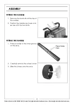
Страница 8: ...ternational com ASSEMBLY FITTING THE HANDLE 1 Remove the two bolts at the top of the welder 2 Position the handle as shown and secure with the two bolts FITTING THE WHEELS 1 Place a circlip on the inner groove on the axle 2 Carefully remove the wheel cover 3 Slide the wheel onto the axle ...

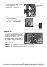
Страница 9: ... 7 Fix the second wheel to the other end of the axle as described DUAL SUPPLY This machine is capable of operating on 230V or 400V single phase the voltage selector is designed so that it can select only one voltage The position of the screw arrowed in the illustration opposite will determine the voltage selection With the screw in POSITION 1 the switch may be turned from O OFF to 400V POSITION 2 ...

Страница 10: ...he two plastic screws to clamp the glass panels from the inside of the mask When replacing the glass panels only use parts supplied by Clarke International The dark panel is a certified specific optical class and should not be exchanged for any other type The clear glass panel should be replaced when it becomes badly pitted PREPARATION FOR USE FITTING THE WELDING ROD 1 Select the appropriate weldi...

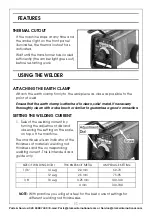
Страница 11: ...the earth clamp is attached to clean solid metal If necessary thoroughly clean with a wire brush or similar to guarantee a good connection SETTING THE WELDING CURRENT 1 Select the welding current by turning the adjustment dial and observing the setting on the scale on top of the machine The chart below is an indicator of the thickness of material welding rod thickness and the corresponding welding...

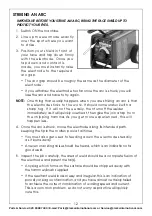
Страница 12: ...come unstuck with a sharp tug If it will not free easily then turn off the welder immediately as it will quickly overheat then give the join a tap from the chipping hammer As you get more experienced this will happen less 4 Once the arc is struck move the electrode along its intended path keeping the tip in the molten pool at all times You must also get used to feeding down the electrode steadily ...

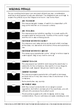
Страница 13: ...and heavy deposit which overlaps at the sides It is wasteful both in terms of time and electrode use ELECTRODE MOVED TOO QUICKLY This causes poor penetration with a stringy and incomplete weld deposit Slag is very hard to remove CURRENT TOO LOW This causes poor penetration and causes the electrode to easily stick to the workpiece Also results in a very irregular and high weld deposit Slag is very ...

Страница 14: ...d be inspected at least annually Consult your CLARKE dealer for advice if necessary DUTY CYCLE This welder is covered by regulations EN60974 1 and EN 50199 where the Duty Cycle X is expressed as a percentage of time the machine may be used in a given period for a specified welding current i e When welding at 80 Amps the machine may be used for 6 minutes 60 in any10 minute period or the machine may...

Страница 15: ...mum supply current 5 British Standards applied 17 Maximum effective supply current 6 Manual metal arc welding with covered electrode 18 N A 7 This symbol indicates that the unit is suitable for carrying out welding operations in an environment which has an increased risk of electric shock 19 N A 8 Welding Current symbol 20 N A 9 Rated no load voltage 21 N A 10 Max welding current and corresponding...

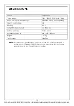
Страница 16: ...int However CLARKE International reserve the right to change specifications at any time without prior notice Model Easiarc 200 Power Supply 230V 400V 50Hz Single Phase Rated Max Input Current I1Max I1eff 45 14 8 A 230V 26 7 3A 400V Open Circuit Voltage 48V IP Rating IP21S Output Min Max Current 60 200 Amps Usable Electrodes 2 mm 4 mm Dimensions l x w x h 498 x 355 x 410 mm Weight 19 6 kg Part Numb...

Страница 17: ...17 Parts Service 020 8988 7400 E mail Parts clarkeinternational com or Service clarkeinternational com DECLARATION OF CONFORMITY ...

Страница 18: ...18 Parts Service 020 8988 7400 E mail Parts clarkeinternational com or Service clarkeinternational com NOTES ...

Страница 19: ...19 Parts Service 020 8988 7400 E mail Parts clarkeinternational com or Service clarkeinternational com NOTES ...

Страница 20: ......

Отзывы: