background image

CDM25 - Page 11

MAINTENANCE

CAUTION:

1. Make sure test leads are dsconnected from the
test drcuit, and range switch is set to OFF before
opening the case.

2. Do not operate the instrument unless the back
cover is in place and fastened.

BATTERY REPLACEMENT

1. When batteries become exhausted, or drop below the

operating voltage, “BATT” sign will appear on the LCD.

2. Turn off meter and remove test leads from dl test

circuits pnor to replacing batteries.

3. Remove the screw from the back cover and open

the case. Replace batteries, ensuring proper
polarity is observed.

REPLACEMENT OF FUSE

Proceed as for changing battery, ensuring the fuse
replacement is of the same size and rating as the original.

Fculure to do so may result in serious damage to your
meter or possibly even fire.

(Fuse must be no more than 0.5A/250V)

REPLACEMENT PARTS

1. Test Leads (pair)

Part No. CHI5O1

2. Fuse (0.5A1250V)

Part No. CH1502

Содержание CDM 25

Страница 1: ...CDM25 Page 1 DIGITAL MULTIMETER Model No CDM 25 OPERATING INSTRUCTIONS 0507...

Страница 2: ...purchase This guarantee is invalid if the product has been abused or tampered with in any way or not used for the purpose for which it is intended The reason for return must be clearly stated This gu...

Страница 3: ...rating Instruction booklet TABLE OF CONTENTS Features 2 Safety Precautions 4 Description of Front Panel 5 Operating Instructions 6 DC Voltage 6 AC Voltage 7 DC Current 8 AC Current 8 Resistance Measur...

Страница 4: ...disconnecting the common test lead Follow all equipment safety procedures Disconnect the input power and discharge all high voltage capacitors through a protective impedance before testing in and with...

Страница 5: ...DESCRIPTION OF PANEL 1 Push Button ON OFF switch 2 D H Push Button for data hold function 3 Rotary Function Switch 4 Test Leads Red positive Black negative polarity 5 3 digit LCD from 0 to 9999 count...

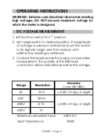
Страница 6: ...ion If magnitude of voltage is unknown beforehand set the switch to its highest range and then reduce until satisfactory reading is obtained 3 Connect test leads across the source or load under measur...

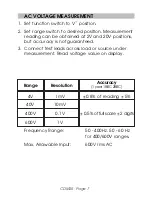
Страница 7: ...2V and 20V positions but accuracy is not guaranteed 3 Connect test leads across load or source under measurement Read voltage value on display 4V 1mV 0 8 of reading 5 40V 10mV 400V 0 1V 0 5 of full sc...

Страница 8: ...18EC 28EC Range Resolution 40mA 0 01mA 400mA 0 1mA Overload Protection 0 5A 250V fuse 2 0 of rdg 2 digits AC CURRENT 1 Set function switch to A position 2 Open the circuit to be measured and connect...

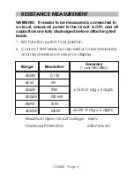
Страница 9: ...scharged before attaching test leads 1 Set function switch to position 2 Connect test leads across resistor to be measured and read resistance value on display 400W 0 1W 4kW 1W 40kW 10W 400kW 100 kW 4...

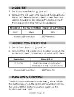
Страница 10: ...ect the test leads to two points of a circuit The buzzer will sound if the resistance is lower than 50 ohms Resolution Description 0 1 ohm Built in buzzer sounds when resistance is less than 50 ohms O...

Страница 11: ...n the LCD 2 Turn off meter and remove test leads from dl test circuits pnor to replacing batteries 3 Remove the screw from the back cover and open the case Replace batteries ensuring proper polarity i...

Страница 12: ...follows PARTS Parts clarkeinternational com SERVICE Service clarkeinternational com Other Clarke quality products include AIR COMPRESSORS WELDERS POWER WASHERS GENERATORS BATTERY CHARGERS BOOSTERS ENG...

Отзывы: