background image

Page  -5-


Clarke

®


 American Sanders


 Operator's Manual - CAV 26

Figure 4

INTRODUCTION AND INSTRUCTIONS, cont.

1

2

3

4

Features

Figure 1, 1 - Control Panel

For explanation of controls, see "Controls" section this page.

Figure 1, 2 - Inlet

This inlet is for installation of vacuum hose and accessories.

Figure 1, 3 and Figure 2, 1 - Debris Canister

The debris canister should be emptied when the canister is full.
To empty canister, lift debris canister lever (figure 3,2).  Debris
canister will lower until it rests with it's wheels on the floor.  Grip
the handle and remove the canister, then empty it's contents.

To fit the canister back in place, set it under the vacuum, making
sure the full sight level gauge (figure 3,1) remains visible from the
outside.  Then push lever (figure 3,2) downwards, allowing the
canister to lift until it fits against filtering chamber.

Figure 1, 4 - Filter Cleaning Lever

This lever is to used to clean the filter.  When manometer (figure
4, 1) reads that the filter is clogged, turn the filter cleaning lever
several times with force in order to shake the dust from the filter.

Do not operate lever with vacuum running.

Wait a few minutes for the dust to settle at the bottom of the
container, then empty.

Figure 3, 1 - Full Sight Level Gauge

This gauge indicates the debris level in the debris canister (figure
1,3).  The debris canister should be emptied when it is full.
Before emptying debris canister, switch off the machine by
pressing the vacuum motor switches (figure 4,2) and remove
plug from the power supply.

Figure 3, 2 - Debris Canister Lever

Lift this lever so that debris canister can be removed and emp-
tied.  Make sure to lower the lever when you replace the debris
canister.

Figure 3, 3 - Balancing Hose

Balances vacuum around polytank liner (fig 2,2), so it's not
sucked into the filter.

Controls

Figure 4, 1 - Manometer to display filter loading

The vacuum in the filter increases proportionally as the filter
clogs.  Then the manometer needle will move from green (filter
good) to the red (filter clogged) section.

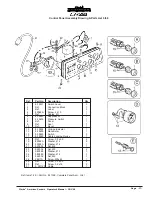
Figure 4, 2 - Vacuum Motor Switches

This model is fitted with 3 motors, so it has three vacuum motor
switches on the control panel.  Press the switches to start the
vacuum motors.  The warning lights (green lights) will come on.
Press the switches again to stop the motors.  The warning light
will go out.

Figure 4, 3 - Electrical Label

Figure 4, 4 - Illuminated Mains Voltage Indicator

When on, this indicates that the vacuum is connected to the
electrical supply.

Содержание CAV 26

Страница 1: ...chine could result in injury to you or to other personnel damage to the machine or to other property could occur as well You must have training in the operation of this machine before using it If your operator s cannot read this manual have it explained fully before attempting to operate this machine All directions given in this book are as seen from the operator s position at the rear of the mach...

Страница 2: ...tions 6 Troubleshooting 8 Section II Parts and Service Manual Frame Assembly Drawing 10 Frame Assembly Parts List 11 Container UnitAssembly Drawing 12 Container UnitAssembly Parts List 13 Suction UnitAssembly Drawing 14 Suction UnitAssembly Parts List 15 Filter GroupAssembly Drawing and Parts List 16 Control Panel Assembly Drawing and Parts List 17 Electrical Schematic 18 ...

Страница 3: ...ndle close a door on the cord or pull cord around sharp edges or corners Do not run machine over cord Keep cord away from heated surfaces Do not leave machine when plugged in Unplug from outlet when not in use or before servicing Do not put any objects into openings Do not use with any openings blocked Keep free of dust lint hair and anything that may reduce airflow Keep hair loose clothing finger...

Страница 4: ... in 61 Weight lbs 143 SPECIFICATIONS INTRODUCTIONANDINSTRUCTIONS The CAV 26 comes fully assembled It is specifically designed for dry pick up of fine dust made from grindings of wood or gypsum It is mounted on tough rubber wheels two of which swivel in order to make the machine easy to handle It also has brakes to safely stop the machine in place NOTE When performance has declined noticeably empty...

Страница 5: ...minutes for the dust to settle at the bottom of the container then empty Figure 3 1 Full Sight Level Gauge This gauge indicates the debris level in the debris canister figure 1 3 The debris canister should be emptied when it is full Before emptying debris canister switch off the machine by pressing the vacuum motor switches figure 4 2 and remove plug from the power supply Figure 3 2 Debris Caniste...

Страница 6: ...outlet than one of those shown in figure 5 Consult an electrician if there is reason to doubt that the wall outlet is not wired correctly Do not remove the grounding pin on the power cord Do not use this appliance with a damaged power cord or plug 3 The CAV 26 uses three individually activated vacuum motors that allow tailoring the delivery for the available electrical supply and application For L...

Страница 7: ... canister becomes full the manometer fig 8 1 reads in the red deactivating all vacuum motors 6 Allow time for the dust to settle then operate the filter cleaning lever fig 9 1 several times 7 Remove the poly liner and replace with a new liner 8 Replace the debris canister To fit the canister back in place set it under the vacuum and push the lever downwards This allows the canister to lift until i...

Страница 8: ...tical character istics 2 Replace it with another with suitable characteristics 1 Remove and replace the carbon brushes 1 Check all ground connections Especially check the suction inlet fitting Lastly the hose must be strictly antistatic 1 No power 1 Clogged primary filter 2 Suction hose clogged 1 The filter is torn 2 Inadequate filter 1 Worn or broken carbon brushes 1 Nonexistent or ineffective gr...

Страница 9: ...Page 9 Clarke American Sanders Operator s Manual CAV 26 Section II Parts and Service 71114A ...

Страница 10: ...Page 10 Clarke American Sanders Operator s Manual CAV 26 Frame Assembly Drawing 2 06 ...

Страница 11: ... 20 229102 Washer Ø 8 2 21 80312A Nut M8 Block 2 22 229102 Washer Ø 8 2 23 80312A Nut M8 Block 2 24 58050A Screw M8 x 65 Soc 2 25 83002A Rivet Ø 6 4 x 15 9 26 98456A Screw M8 x 50 4 27 229102 Washer Ø 8 4 28 80163A Nut M8 4 29 80314A Screw M8 x 65 4 30 229102 Washer Ø 8 4 31 80163A Nut M8 4 32 920936 Nut M12 2 33 980648 Washer Ø 12 2 34 80315A Screw M10 x 65 2 35 229044 Washer Ø 10 2 36 80162A Nut...

Страница 12: ...Page 12 Clarke American Sanders Operator s Manual CAV 26 Container Unit Assembly Drawing 2 06 ...

Страница 13: ...ew M5 x 25 2 17 58414A Screw M5 x 30 1 18 Ref Push Button 1 19 80312A Nut M8 Block 4 20 424033 Washer Ø 8 x 32 4 21 964058 Screw M8 x 16 4 22 80214A Screw M6 x 12 4 23 8 40881 Reducer M6 x 8 2 24 8 40187 Ring Nut 2 25 830331CS Debris Canister Asm Includes 23 33 1 26 8 40771 Handle 2 27 8 17021 Bumper 4 28 8 40001 Wheel 4 29 964058 Screw M8 x 16 4 30 229102 Washer Ø 8 4 31 920936 Nut M12 4 32 87101...

Страница 14: ...Page 14 Clarke American Sanders Operator s Manual CAV 26 Suction Unit Assembly Parts List 2 06 ...

Страница 15: ...3 8 14271 Spacer 1 24 8 35049 Motor Platform 1 25 980646 Washer Ø 6 4 26 88208A Screw M6 x 10 2 29 88208A Screw M6 x 10 2 30 56446A Screw 4 8 x 19 6 31 88208A Screw M6 x 10 4 32 Ref Label 1 33 Ref Label 1 34 80162A Nut M10 1 35 8 14052 Nut 1 36 8 39594 Cable Gland 1 37 80065A Screw M4 x 8 1 38 920934 Nut M4 1 39 8 14499 Spacer 1 40 8 14509 Spacer 1 41 8 38036 Rivet M6 3 42 80214A Screw M6 x 12 3 4...

Страница 16: ... Manual CAV 26 Filter Group Assembly Drawing Parts List 3 06 Ref Part No Description Qty 1 8 17026 Seal 1 2 Ref Tie 6 3 Ref Ring 1 4 Ref Tie 1 5 Ref Filter 1 6 8 17749 Filter Liner Polyester 1 Ref Items 1 5 Part No 8 33151 Complete Filter Qty 1 ...

Страница 17: ...Switch 1 8 Ref Panel 1 9 Ref Seal 1 10 Ref Decal 1 12 8 39526 Voltage Indicator 1 13 8 40400 Manometer 1 15 8 39525 Switch 3 17 8 39529 Cable Locking Device 1 18 Ref Screw 3 9 x 9 5 2 19 80058A Washer Ø 4 2 20 80058A Washer Ø 4 1 21 920934 Nut M4 1 22 924004 Nut M5 2 23 980982 Washer Ø 5 1 24 980982 Washer Ø 5 1 25 924004 Nut M5 1 26 58411A Screw M5 x 25 1 29 Ref Screw 3 9 x 9 5 2 30 Ref Screw 3 9...

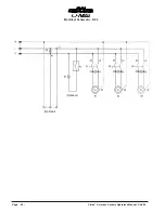
Страница 18: ...Page 18 Clarke American Sanders Operator s Manual CAV 26 Electrical Schematic 6 06 Optional Optional ...

Страница 19: ...erland B V Postbus 65 3370 AB Hardinxveld Giessendam The Netherlands 31 184 677 200 ALTO Sverige AB Molndal Sweden Aminogatan 18 Box 4029 S 431 04 Molndal 46 31 706 73 00 ALTO Norge A S Oslo Norway Bjornerudveien 24 N 1266 47 2275 1770 U S A Locations European Locations CORPO PRODUCTION FACILITIES Clarke Springdale Arkansas 2100 Highway 265 Springdale Arkansas 72764 479 750 1000 Customer Service 1...

Страница 20: ... nearest Clarke American Sanders repair location Transportation charges to and from the repair location must be prepaid by the purchaser c Clarke American Sanders will repair the product and or replace any defective parts without charge within a reasonable time after receipt of the product Clarke American Sanders s liability under this warranty is limited to repair of the product and or replace me...

Отзывы: