


6
7.
Feed the inlet end of the hose through the guide rollers and the slot in the drum.
8.
Apply some teflon sealing tape or thread sealant to the hose connector and connect the air
inlet valve.
9.
Attach the hose clamp to the drum and rewind the hose onto the reel using normal
operation.
C Hose Recoil Tension Adjustment
1.
Disconnect incoming air supply.
2.
Pull out about 2 feet of hose and latch the reel.
3.
Remove hose stopper (part 28).
4.
Firmly hold the edge of the reel drum and unlatch the reel. carfully allow drum to slowly
rewind, drawing the hose end back through the guide arm roller assembly and onto the reel.
Latch the reel in position.
5
To increase tension:
Unlatch reel and turn clockwise (as viewed from the air inlet side).
To decrease tension:
Unlatch and allow reel to rotate anti-clockwise (as viewed from the air
inlet side).
6.
Once the desired spring tension is reached, latch reel in position. Feed hose end through
the roller assembly in guide arm and re-attach hose stopper.
7.
Re-connect incoming air supply.
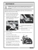
D Replacing the Spring Canister
1.
Follow steps 1-4 under Recoil Tension Adjustment above.
2.
Unlatch the reel and allow the drum to slowly rewind until the tension in the spring is relieved
and the reel stops. Carefully control the speed of the drum and do not release while re-
winding.
3.
Remove the air inlet valve and spacing washer. Refer to A. Replacing the Air Inlet Valve O-
rings: step 2.
4.
Remove nuts from mounting bracket side of drum inside drum cavity. Do not attampt to
remove spring canister nuts on air inlet side of drum.
5.
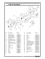
Pull entire spring canister (1) off the drum axle (13). Replace with a new spring canister.
6.
Reverse the above procedure to re-assemble.
7.
After assembly, re-tension the reel by turning the drum three complete turns clockwise (as
viewed from air inlet side) and latch the reel.
8.
Feed the hose through the guide arm and re-attach the hose stopper.
IMPORTANT! If the rewind spring fails for any reason, it is strongly recommended
that, for safety reasons, it is replaced by a trained technician, or returned to your
Clarke dealer for repair.