Clarke 6015200 Скачать руководство пользователя страница 14

14

Parts & Service: 020 8988 7400 / E-mail: [email protected] or [email protected]

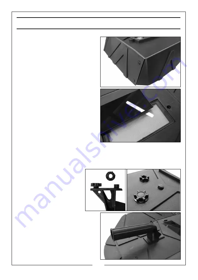
ASSEMBLING THE WELDING SHIELD

1. The welding shield shown on 

page 12 is supplied flat for 
shipping. Fold the sides of the 
shield around and clip to the top 
panel.

2. Insert both the glass lens panels 

into the recess inside the shield.

• The clear glass must be fitted 

first to face the outside.

3. Insert the two plastic screws and 

use the plastic wingnuts to clamp 
the glass panels to the shield.

The clear glass panel should be 
replaced when it becomes badly 
pitted.

4. When replacing the glass panels, only use parts supplied by Clarke 

International. The dark panel is a certified, optical glass and should not be 
exchanged for any other type.

5. Secure the handle in 

position using the plastic 
nuts provided.

The handle will be on the 
inside of the shield.

Содержание 6015200

Страница 1: ...OPERATION MAINTENANCE INSTRUCTIONS ORIGINAL INSTRUCTIONS GC1121 rev 11 NO GAS GAS MIG WELDER MODEL NO MIG196 PART NO 6015200...

Страница 2: ...of purchase This guarantee is invalid if the product is found to have been abused or tampered with in any way or not used for the purpose for which it was intended Faulty goods should be returned to t...

Страница 3: ...ead shields MUST comply with PPE Directive 89 686 EEC B TOXIC FUME PREVENTION Severe discomfort illness or death can result from fumes vapours heat or oxygen enrichment or depletion that welding or cu...

Страница 4: ...areas ventilators If the work cannot be moved move combustibles away from sparks and heat or protect against ignition with suitable fire resistant covers or shields Walls ceilings and floor near work...

Страница 5: ...se from gas shielded arcs are more severe and painful DON T GET BURNED FOLLOW ALL SAFETY PRECAUTIONS PROTECTIVE CLOTHING Wear long sleeved clothing particularly for gas shielded arc in addition to glo...

Страница 6: ...rittle area that can cause a violent rupture or lead to such a rupture later under rough handling D SHOCK PREVENTION Exposed live conductors or other bare metal in the welding circuit or in unearthed...

Страница 7: ...oin welding cable 4 CABLES Frequently inspect cables for wear cracks and damage IMMEDIATELY REPLACE those with excessively worn or damaged insulation to avoid possibly lethal shock from bared cable Ca...

Страница 8: ...clothes should be worn at all times 3 ALWAYS check that the pressure regulator and gauges where fitted are working correctly DO NOT lubricate the regulator 4 ALWAYS use the correct regulator Regulator...

Страница 9: ...o cool 16 NEVER connect disconnect or attempt to service the welding torch until the machine is switched OFF and disconnected from the mains supply 17 NEVER allow the earth cable or torch hose to beco...

Страница 10: ...al which is marked N Connect the brown wire to the terminal which is marked L Connect the Yellow and Green wire to the terminal which is marked E or We recommend that this machine is connected to the...

Страница 11: ...e 1 x Handle Cap 1 x Handle Fixings Pack 3 x Copper Torch Tips 2 x 0 8 mm 1 x 1 0 mm fitted Mild Steel Wire Mini Spool 0 6mm Flux cored mild steel wire mini spool 0 9 mm 1 x Instruction Manual 1 x Whe...

Страница 12: ...he side panel by pushing the latch down and allowing the side panel to drop down 2 Remove any loose items that have been transported inside such as the handle wheel kit etc NO DESCRIPTION NO DESCRIPTI...

Страница 13: ...10 minutes the power will be restored and welding can recommence 2 Power ON OFF switch When the power is ON the green switch will be illuminated When the welder is no longer required the Power On Off...

Страница 14: ...the shield The clear glass must be fitted first to face the outside 3 Insert the two plastic screws and use the plastic wingnuts to clamp the glass panels to the shield The clear glass panel should be...

Страница 15: ...R USE FITTING THE WHEELS 1 Fit two e clips onto the axle in the positions shown 2 Slide the axle into the wheel supports 3 Fit two e clips onto the opposite end of the axle in the same positions 4 Rem...

Страница 16: ...e panel by pushing the latch down and allowing the side panel to drop down 2 Remove the locking knob and retaining disc 3 Place the spool of welding wire not supplied over the spindle so that it sits...

Страница 17: ...roller back on the spindle with your chosen side facing you 6 Replace the drive roller cover back onto the drive spindle with the opening facing right 7 Ensure that the flanges at the base of the driv...

Страница 18: ...rew the contact tip 8 Connect the welder to the power supply and switch ON 9 Set the WIRE FEED rotary control on the front panel to position 7 or 8 and squeeze the trigger on the torch body The wire w...

Страница 19: ...and as a filler The gas is used to prevent oxidation and to shield the arc and the weld from atmospheric contamination The choice of gas is dependent upon the material being welded Two types are avai...

Страница 20: ...wire connect the terminal as shown The earth cable Thicker Lead should be connected to the negative Black terminal The cable from torch Thinner Lead should be connected to the positive Red terminal C...

Страница 21: ...ur workpiece until you are satisfied with the result and you have fine tuned your welder to produce a satisfactory weld NOTE One of the problems experienced with novice welders is the welding wire sti...

Страница 22: ...ing the example shown which is an illustration of the data plate e g when welding at 40 amps the machine may be used for 6 minutes 60 in any 10 minute period WELDING HINTS Try to maintain the tip of t...

Страница 23: ...ove removing all dust deposits Torch Protect the torch hose assembly from mechanical wear Clean the liner from the machine forwards by using compressed air If the liner is blocked it must be replaced...

Страница 24: ...ize Welder does not feed wire Feed motor has malfunctioned Return welder to your local dealer Feed motor running but no wire being fed from welder tip Insufficient Feed Roller pressure Increase roller...

Страница 25: ...tension roller Caution Do not over tighten Wire dirty rusty damp or bent Re cut wire and ensure it is clean Liner partially blocked Clean with compressed air Poor quality welds Insufficient gas at wel...

Страница 26: ...imum supply current 5 British Standards applied 17 Maximum effective supply current 6 Welding process 18 N A 7 This symbol indicates that the unit is suitable for carrying out welding operations in an...

Страница 27: ...y cycle must be adhered to prevent the thermal cutout protection from activating Do not exceed the stated duty cycle for this machine Failure to heed this warning may invalidate your warranty Model MI...

Страница 28: ...Part Description Part number Comment Welding Wire Spools Flux cored mild steel mini spool 0 9mm 8132110 Use for no gas welding Mild steel mini 0 6mm 8132100 Use for gas welding Mild steel mini 0 8mm 8...

Страница 29: ...S These highly popular headshields activate instantly when the arc is struck and allow you to have both hands free when welding Model Arc Activated Grinding function Solar Powered Fixed Shade Flip Up...

Страница 30: ...30 Parts Service 020 8988 7400 E mail Parts clarkeinternational com or Service clarkeinternational com DECLARATION OF CONFORMITY UK...

Страница 31: ...31 Parts Service 020 8988 7400 E mail Parts clarkeinternational com or Service clarkeinternational com DECLARATION OF CONFORMITY EU...

Страница 32: ......

Отзывы: