Clarity SN-4215-P Скачать руководство пользователя страница 55

3 - 35

unit. Turn off its Color Balance menu. 

10. Choose another variable unit next to any

baseline display and match it in white.

11. When all displays match in white, Open

the Test Patterns menu again and choose

50% Gray

 for all of them.

12. The gray values range from 000 to 015,

and they are all now set at 007. Therefore,

gray can be adjusted up and down. Choose

a display that has a middle brightness and

that has very little color in the gray. This

13. becomes the first baseline display for gray.

It is not necessarily the same one as the

first white baseline unit. 

14. Proceed as before, matching the grays one

display at a time, always working with

adjacent displays. 

15. When all displays match in gray, open all

the Test Pattern menus and choose 

Off

16. For all displays, save these settings. See

Section 3.5 on page 3-34.

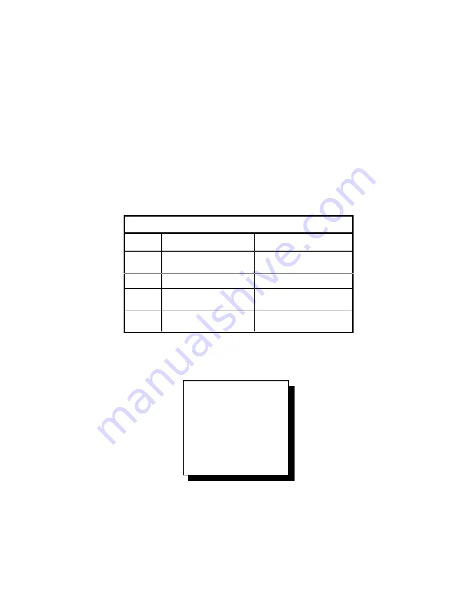
How to Adjust the “Color” of White and Gray

Color

Increasing it will …

Decreasing it will …

All

increase the total

brightness

decrease the total

brightness

Red

make the white more red

make the white more cyan

Green

make the white more

green

make the white more

magenta

Blue

make the white more

blue

make the white more

yellow

Color Balance

Wht

Gry

All

← → 

 → 

 → 

 → 

 ← → 

 ← → 

 ← → 

 ← → 


Red

031

007

Green

031

007

Blue

031

007

Color Balance menu

Содержание SN-4215-P

Страница 1: ... SN 4215 P 42 SignPost Plasma Display User s Guide 070 0038 01 08 June 2000 ...

Страница 2: ...ademarks or registered trademarks of their respective companies Disclaimer The information contained in this document is subject to change without notice Clarity Visual Systems Company makes no warranty of any kind with regard to this material While every precaution has been taken in the preparation of this manual Clarity Visual Systems shall not be liable for errors or omissions contained herein ...

Страница 3: ... exist and were not caused by accident misuse neglect alteration improper installation repair or improper testing Clarity will have a reasonable time to make repairs to replace Products or to credit Buyer s account LIMITATIONS Any written warranty offered by clarity is in lieu of all other warranties express or implied Clarity neither assumes nor authorizes any other person to assume any other lia...

Страница 4: ... Detect for PC Sources 3 14 3 2 2 Selecting Video Sources 3 16 3 3 Adjusting for Optimum Picture Quality 3 18 3 3 1 Input Levels Computer Sources 3 20 3 3 2 Frequency Phase Computer Sources 3 22 3 3 3 Input Adjustments Video Sources 3 24 3 4 Saving and Recalling the Settings 3 26 3 5 Adjusting Displays in a Video Wall 3 28 3 5 1 Filling the Wall With One Image 3 30 3 5 2 Adjusting Position and Siz...

Страница 5: ...6 6 7 References 7 1 7 1 RS232 Commands 7 2 7 2 Menus 7 4 7 3 Connector Pinouts 7 10 7 4 LEDs 7 11 7 5 Regulatory Information 7 12 7 6 Specifications 7 14 7 7 Making Test Patterns With Paint 7 18 7 8 Technical Support Forms 7 20 Index 7 23 ...

Страница 6: ...vi vi ...

Страница 7: ...1 1 1 Information You Need to Know 1 1 What is the SN 4215 P 1 2 Your Safety Is Important ...

Страница 8: ...y and makes installation more flexible Be sure to read about Image Retention page 2 2 The SN 4215 P screen has a 16x9 aspect ratio and the electronics module accepts a variety of input types SN 4215 P Signal Types Signal Frequency Signal Format 640x480 VGA 800x600 SVGA crop ped 852x480 832x624 cropped 640x400 RGB H V sync sepa rated RGB composite sync RGB sync on green 525 60 NTSC composite or S v...

Страница 9: ...pply Module with connecting cable 1 Mounting bracket for the back of the display 1 Mounting bracket for the wall 3 6 32 x Phillips head screw 3 20 x socket cap screw 2 8 32 x 2 standoff 1 VGA cable 15 pin D sub 1 AC Power cord 1 Remote control with batteries 1 User s Guide this manual ...

Страница 10: ...rd the power supply produces some pret ty high voltages Never turn on the power sup ply switch unless it is connected to the display Do not open the back of the display There are no user serviceable parts inside Transporting the display Always always always transport the display vertically Never never never transport it lying flat The display was shipped to you vertically and that is the way it sh...

Страница 11: ...1 5 WARNING Disconnect power cord before servicing this unit WARNING When mounting the display on the wall be sure to mount it to wall structures not to wall board or paneling ...

Страница 12: ...1 6 ...

Страница 13: ...2 1 2 How to Install the Displays 2 1 Before You Start 2 2 Installing the Displays 2 3 Connecting Power and Signal Cables ...

Страница 14: ...t produce burn in Any application where the same thing will be shown in the same part of the screen for a long time For example Each picture is on the screen for more than one or two minutes Text displays where the headline or some other part never changes even though the rest of the text continually changes Moving images in which the background never changes such as the background in video confer...

Страница 15: ...be displayed for more than one or two minutes Avoid moving images where one part of the scene does not move High contrast images burn in faster and stronger than low contrast images If using still images keep the cycle time at no more than one minute per image ...

Страница 16: ...tion using the brackets supplied the top of the display will be 1 7 8 4 8 cm higher than the row of mounting holes in the wall bracket When mounted and hung in portrait orienta tion the top of the display will be 9 1 2 24 1 cm higher than the row of mounting holes in the wall bracket When you plan the installation leave at least 1 3 4 4 5 cm of space above the top of the display This will allow yo...

Страница 17: ...o wall Mounting bolt Wall At least 1 3 4 to ceiling Mounting the display panel in landscape orientation SN 4215 P Bracket on rear of display Bracket mounted to wall Wall At least 1 3 4 to ceiling Mounting bolt 9 1 2 Mounting the display panel in portrait orientation ...

Страница 18: ...ctor to the display s PC type connector 2 If there is a second computer source con nect it to PC2 3 For video sources connect a composite video source usually a round connector with only one central pin to the C Video input Connect S Video sources to the S Video connector 4 If you are using more than one SN 4215 P display you can loop the signal from one display to the next For computer sources co...

Страница 19: ...2 7 Rear panel of display Video inputs with their loop thru outputs RS232 input and output PC inputs with their common loop thru output Power input connector on rear panel ...

Страница 20: ...2 8 ...

Страница 21: ...ect for PC Sources 3 2 2 Selecting Video Sources 3 3 Adjusting for Optimum Picture Quality 3 3 1 Input Levels Computer Sources 3 3 2 Frequency and Phase Computer Sources 3 3 3 Input Levels Video Sources 3 4 Saving and Recalling the Settings 3 5 Adjusting Displays in a Video Wall 3 5 1 Filling the Wall with One Image 3 5 2 Adjusting Position and Size Zoom 3 5 3 Matching the Colors 3 6 Some Addition...

Страница 22: ...se Do this for computer sources only p 3 22 It matches the electronics module s internal clock to the external computer signal 4 Save the Settings Save the settings as you work Each input has a separate mem ory so you can setup for two computers and save all the settings for them sepa rately one on each connector It is a good idea to save the settings several times as you go through the setup proc...

Страница 23: ...3 3 ...

Страница 24: ...the circuit breaker on the power sup ply is on The MENU button opens the main menu on the screen From this menu you high light an item with the up down arrows Then press ENTER to activate the high lighted selection The PREV MENU button closes the current menu and keeps the parent menu if there is one If there isn t a parent menu this button removes the last menu ENTER has several actions which dep...

Страница 25: ... of display front LEVEL ID MON SEL PREV MENU MENU ENTER OFF COLOR FREQ CURTAIN PHASE SOURCE ON RESET These controls are also found in the Main Menu These two controls are not found in the Main Menu This opens the Main Menu Select or activate a feature Back up one menu level Adjust a value Move through the menu The Remote Control ...

Страница 26: ...automatically illuminate at the end of the lockout period This means that if the unit loses power it will auto matically come back on and illuminate without waiting for an external ON command IR Activity The IR Activity LED flickers whenever the display electronics detects any infra red radia tion If this LED is continually lit it indicates stray IR radiation coming from something else such as xen...

Страница 27: ...rs Save Config Recall Config Reset Config Misc Control About Main menu Misc Control x Sharpness x 16M Colors x Buzzer Enable Auto Panel On Viewport Color Test Patterns Temperature Baud Rate Auto Controls Misc Control menu Meaning of the LEDs LED Meaning Standby Flashes during Standby lockout period On steady when waiting for external ON command Off when the panel is on Good Source On when the sele...

Страница 28: ... 3 10 lets you choose which input PC1 or PC2 to use The electronics can automatically set all the necessary parameters such as choosing between 640x480 800x600 and others Connect a computer source to either PC1 or PC2 input For MAC or RGB sources use an adapter if necessary to convert to the VGA pin arrangement Video connections If the video option is installed the back of the display has two vide...

Страница 29: ...ssive H V H Freq 37249 Lines 629 V Freq 60 Figure 26Source Select menu when choosing a computer source Source Select Source C Video PC1 NTSC PC2 Current C Video Mode Detect S Video Interlace C o m p o s i t e H Freq 15734 Lines 623 V Freq 60 Source Select menu when choosing a video source ...

Страница 30: ...ces and a bullet dot shows what is currently selected 4 The electronics will now automatically choose the correct Mode in this case res olution to display the picture 640x480 VGA 800x600 SVGA 832x624 a MAC resolution 852x480 fits the screen exactly 640x400 Windows resolution during shutdown It will also choose the correct Scan Pro gressive or Interlace and the correct Sync type H V on separate lin...

Страница 31: ... Detect 852x480 Progressive 640x400 H V H Freq 37429 Lines 629 V Freq 60 Mode is usually selected automatically Source Select Detect PC1 800x600 Current Mode Detect Progressive H V H Freq 37429 Lines 629 V Freq 60 Mode Detect is automatic unless you defeat it Source Select Format PC1 Current 800x600 Normal Current Wide Mode Detect Zoom Progressive H V H Freq 37429 Lines 629 V Freq 60 Use Format to...

Страница 32: ...ecome flattened ellipses Zoom Zoom in on the picture until the sides of the picture meet the sides of the screen This will chop off the top and bot tom of the picture To choose one of these Formats 1 open the Source Select menu by pressing SOURCE 2 Press the down arrow twice to get to the third item on the left side of the menu The label at the top of the right side will now say Format 3 Use the l...

Страница 33: ...ere are unused bands on left and right Wide Format The picture is stretched horizontally to fill the screen causing distortion Zoom Format The picture is stretched in both directions to fill the screen There is no distortion but the top and bottom are clipped ...

Страница 34: ...ct in the Source Select menu and press ENTER Message Enable when it has an x displays as message on the screen just above the Source Select menu that tells you what Mode Detect is doing When Mode Detect is active it tests for the different types of sync H V Composite or Sync on Green The message displays which of these it is currently testing The left right arrows change the number of sec onds sho...

Страница 35: ...PC1 800x600 Normal Mode Detect Progressive H V H Freq 37429 Lines 629 V Freq 60 Auto Detect x Auto Enable x Message Enable Noise Tolerance 004 While the Source Select menu is open press SOURCE button to open the Auto Detect menu ...

Страница 36: ...units or 15 inches wide Note 1 33 1 and 4x3 are two ways of describing the same aspect ratio Similarly 1 77 1 and 16x9 are the same which is the aspect ratio of the SN 4215 P screen How to choose Aspect Ratio Format It is easy enough to change the aspect ratio of the picture display Simply highlight the third item in the menu so the right side says For mat and use the left right arrows to change i...

Страница 37: ...rlace Composite H Freq 15734 Lines 623 V Freq 60 Source Select menu when choosing a video source Source Select Mode C Video NTSC NTSC PAL Current SECAM Mode Detect Interlace Composite H Freq 15734 Lines 623 V Freq 60 Mode is selected automatically Source Select Format C Video Current NTSC 1 33 1 Current 4x3 Mode Detect 1 77 1 Interlace 16x9 Composite 1 85 1 2 35 1 H Freq 15734 Lines 623 V Freq 60 ...

Страница 38: ...the video card in the computer connected to the display 4 you change the display connection from one video card to another 5 you change video sources 6 you change the display connection from one video DA to another video DA even if these connection are on the same DA output card Note DO NOT use the Input Level adjustments to make color adjustments Color adjustments getting the units to match in co...

Страница 39: ...3 19 For computer sources adjust Input Black Level Input White Level Frequency For video sources adjust Brightness Contrast Hue Saturation ...

Страница 40: ...y dark gray When in doubt make a black signal with Windows Paint as described on page 7 18 2 On the remote press LEVEL This opens the Black Level menu Black must be done before White 3 Highlight Auto and press ENTER In less than two seconds the electronics will automatically detect the incoming signal s black level and adjust to it Note Do not be concerned with the numbers listed in the Level colu...

Страница 41: ...Red 127 000 Green 123 001 Blue 131 000 2 Highlight Auto and press ENTER 3 Press LEVEL again Finished White Level Requires white field Auto All Level Sample Red 127 254 Green 123 255 Blue 131 255 4 Highlight Auto and press ENTER 5 Press LEVEL again 1 Press LEVEL ...

Страница 42: ...ontrol and press ENTER 4 See that Sharpness has an x in it If it doesn t highlight it and press ENTER 5 On the remote press FREQ 6 Adjust Frequency with the right left arrow keys When the frequency is wrong you will see vertical bands of noise in the picture If there is horizontal streaking as well ignore that for now As you change frequency the number of bands will increase or decrease At one fre...

Страница 43: ...L ID MON SEL PREV MENU MENU ENTER OFF COLOR FREQ CURTAIN PHASE SOURCE ON RESET Frequency and Phase M enus Frequency and Phase buttons Phase Select 016 Phase Select menu Frequency Select 064 Frequency Select menu ...

Страница 44: ... frame 50882 on Reference Recordings A Video Standard test disk has this picture 5 Highlight Brightness and adjust it with the right left arrows Make the R G and B values as close to 001 as possible and keep the Brightness number as high as possible If the initial Sample values are greater than 001 reduce the Brightness until the first Sample value reaches 001 If the initial Sample values are 001 ...

Страница 45: ...y only shades of blue 10 Adjust Saturation up or down until the two outside blue bars which were white and blue are the same 11 Adjust Hue up or down until the two inside blue bars which were cyan and magenta are the same 12 Video Track is a little like the tracking control on a VCR It has four settings 000 through 003 Choose setting that gives the most steady picture 13 Exit the menus with the PR...

Страница 46: ...ee places where settings are stored The first storage place is the Active Settings This is what the unit is actually doing when it is on If you change anything this is where the change occurs Actually the Active Settings isn t really a memory When the power goes off everything in this register is lost However on power up the Saved Memory is copied into Active Settings The second storage place is S...

Страница 47: ...mory Factory Default Values Save Reset Recall Relationship of Active Settings Memory and Default Recall Config Recall PC1 Recall 2 Arrow down press ENTER Recall Config Sure PC1 Recall Are you sure Yes No 3 Arrow left to highlight Yes press ENTER Recall Config Sure PC1 Recall Are you sure Recall Settings 4 Finished red message shows for a few seconds ...

Страница 48: ...s is called Color Balancing It is not necessary to match each individual color You only have to match the units for white and for gray When the whites and grays match the rest of the colors will match It is also not necessary that the white be a perfect white The White Pages of a telephone book are a long way from white but they are certainly white com pared to the Yellow Pages The SN 4215 P has v...

Страница 49: ...29 Making a Video Wall Install the display units together Use Clarity s Big Picture to make one image cover the wall or use an external processor Adjust Position and Size as needed Color Balance the wall ...

Страница 50: ...ng in Western cultures The diagram shows a 4x4 wall viewed from the front and numbered correctly for Big Picture The numbers are hexadecimal the larg est number is in the lower right corner 0F hex 15 decimal For walls larger than 16 units use the Group ID number so the 17th display would be number 10 3 In each display turn on Wall Processor from the main menu MENU Wall Processor 4 Set the Horizont...

Страница 51: ...rocessor Wall Size Horizontal 002 Vertical 002 Current Unit 01 Misc Calc wall pos Wall mode What you see if Clarity s Big Picture is installed Monitor ID Group 0 Unit 1 ID menu Press ID on the remote to get to this menu The Big Picture option is not installed Please see the About menu for contact information on purchasing the Big Picture option What you see if Clarity s Big Picture is not installe...

Страница 52: ... pixel increments horizontally The Zoom menu controls the size of the image on the screen but it is not the only thing that does this In the Source Select menu the Format controls Wide and Zoom for computer sources aspect ratio of video sources also do some zooming And of course Big Picture zooms in on the image To control zoom manually open the Zoom Factor menu by pressing MENU Zoom In this menu ...

Страница 53: ...3 33 Position Image Viewport Position menu ENTER switches between Image and Viewport Zoom Factor Left W xxxx Right Top H xxxx Bottom Lock Default Zoom menu ...

Страница 54: ...ys look alike when they display white and gray Color Balancing 1 Turn on all the units in the wall and let them warm up for at least five minutes 2 On each display select Misc Controls from the main menu Then choose Test Patterns and press ENTER 3 On each display choose the White test pattern 4 On each display open the Color Balance menu by pressing the COLOR button on the remote Note In this menu...

Страница 55: ...rily the same one as the first white baseline unit 14 Proceed as before matching the grays one display at a time always working with adjacent displays 15 When all displays match in gray open all the Test Pattern menus and choose Off 16 For all displays save these settings See Section 3 5 on page 3 34 How to Adjust the Color of White and Gray Color Increasing it will Decreasing it will All increase...

Страница 56: ...he left and right arrow keys The two ID settings identify the display unit for RS232 commands Group and Unit are hex numbers ranging from 0 to F 0 to 15 decimal Normally all displays in one video wall are set wit the same Group number and the Unit numbers start with 0 at the upper left corner increase to the right and down like reading in western cultures ending with the highest number in the lowe...

Страница 57: ... black immediately The CURTAIN button or Curtain ENTER also remove the curtain and the pictures shows again Hours opens a menu that shows the number of hours the panel has been illuminated and the number of hours the electronics module system hours has been powered up You can reset Panel Hours if you replace the display panel itself but you can t change System Hours To reset Panel Hours 1 Open the...

Страница 58: ... lamp won t light Auto Panel On means the unit will try to illuminate after the electronics module gets power and after some initialization procedures and a short delay time If this box is not checked the electronics module goes into a standby mode the Standby LED stays on and the unit waits for an ON command Viewport Color determines the color of the blank part of the screen when viewing images t...

Страница 59: ... must match the baud rate of the computer that is sending and receiving RS232 commands Otherwise com munication is not possible Auto Controls opens the menu described in Section 3 2 1 2 About Auto Detect for PC Sources on page 3 14 Temperature Sensor Low Temp xxxx High Temp xxxx Curr Temp xxxx Baud Rate Menu 9 6Kpbs 19 2Kbps 38 4Kbps 57 6Kbps ...

Страница 60: ...3 40 ...

Страница 61: ...4 1 4 Controlling the Displays Remotely 4 1 How RS232 Commands Work ...

Страница 62: ...and The address is divided into a Group Address 1st byte and Unit Address 2nd byte There are four possible address forms Single address The whole address is specified such as 00 01 A3 FF Only the single display that matches this address attempts to execute this command and an ACKnowledgment is sent Note In single address mode the host computer should wait for an ACK NAK UNK or ERR response before ...

Страница 63: ...h ETX and the time from STX to ETX must be less than one second The ID number for each display is set with the remote control Press the ID button This will open a menu where you can highlight either number with the up down buttons and change it with the right left buttons RS232 command structure Start of transmission Group and Unit Identification Command End of transmission STX IDT CMD ETX 1 byte ...

Страница 64: ...4 4 ...

Страница 65: ...5 1 5 Maintenance 5 1 Cleaning and Transportation ...

Страница 66: ... on the cloth not the glass Always use a new clean cloth or a new lint free paper wipe Old cloth that has previously been used for cleaning often contains grit too small to see which can scratch the glass Transporting the display WARNING Never transport the display laying flat Always ship or transport it vertically The display screen itself is the most expensive part of the unit and if the glass b...

Страница 67: ...5 3 Carry the panel like this not like this ...

Страница 68: ...5 4 ...

Страница 69: ...6 1 6 Troubleshooting 6 1 Power and Startup Problems 6 2 Image Problems 6 3 Common Questions and Answers ...

Страница 70: ...ike you don t have a picture but the problem is not in the display unit itself If the picture source is disconnected from the Input there won t be a picture If the wrong source is selected there may not be a picture Use Source Select to look at all the input connectors Note When unit first detects that there is no source a SOURCE ABSENT sign stays on the screen for about 10 seconds After 10 second...

Страница 71: ...ected to panel Check voltage at wall outlet Turn power supply switch off then on again 4 Display goes into a ready state Standby LED stays on without flashing If Auto Panel On is enabled in Misc Controls menu display will turn on and Standby LED will go out 5 Send ON command to display Use remote and press ON Buzzer beeps once Fans start Standby LED flashes a few times then goes off Display turn o...

Страница 72: ... See page 3 34 Previous image still visible as a ghost This is burn in Display a white image for five minutes to see if this clears up the burn in Use a plain white image without any other picture information Image gets darker over time This is normal It preserves the screen and reduces use of electricity Whenever a bright image is displayed it slowly becomes dimmer after about 10 seconds The menu...

Страница 73: ...6 5 ...

Страница 74: ...vice help Contact the company that sold you the displays One of the LEDs is flashing Does that mean trouble It may mean something isn t right The Standby LED flashes for a short period during initial power up When it is steady the unit is waiting for an ON command The IR Remote Sensor LED flashes whenever the unit detects infra red radiation whether it comes from the remote control or not One of t...

Страница 75: ...an SVGA source No VGA 640 x 480 only How do I find a qualified service person Contact the company that sold you the display We bought our Clarity displays from Company name Address Sales Person Phone Technician Phone ...

Страница 76: ...6 8 ...

Страница 77: ...7 1 7 References 7 1 RS232 Commands 7 2 Menus 7 3 Connector Pinouts 7 4 LEDs 7 5 Regulatory Information 7 6 Specifications 7 7 Making Test Signals with Paint 7 8 Technical Support Forms ...

Страница 78: ...lay hours dialog box Read Lamp Hours high byte LH Read Lamp Hours low byte LL Lamp Hours Reset LRS Reset Lamp Hours to zero Read System Hours high byte TH Read System Hours low byte TL Source Controls Save All Settings SAA Recall All Settings RCA Reset All Settings RSA Input Level Offset Controls Display Input Level White Menu LVW Auto adjust White Input Level AWL Input White Level Adjust ALL LAU ...

Страница 79: ...ed 5 Green 6 Blue 7 Geometry 10 Gray Ramp Test Signal White Field WHT Test Signal Black Field BLK Test Signal 50 Gray Field GRY Test Signal Red Field RED Test Signal Green Field GRN Test Signal Blue Field BLU Test Signal Geometry Test Signal Gray Ramp GE4 Test Signal TS 0 off 1 on Test Signal Data Red TR Set test signal red level 0 255 Test Signal Data Green TG Set test signal green level 0 255 Te...

Страница 80: ... Level menu the gateway to the Black Level and White Level menus Zoom Opens the Zoom adjustment box where the image can be stretched or compressed on any one of the four sides Position Opens the Position box where the image may be moved electronically Color Balance Opens the Color Balance menu where the brightness and color of the displays are matched to each other Curtain Opens a Curtain Select b...

Страница 81: ...rce for automatic setup Not functional grayed out when video a source is selected S c a n Scan is one of the following Progressive Interlace Not functional grayed out and forced to Interlace when video a source is selected S y n c Sync is one of the following H V Sync is on two separate wires in the cable Composite Sync is combined with the picture signal Sync Green Sync is on the Green channel of...

Страница 82: ...shown does not directly correlate to phase Input Level Black Level Opens Black Level menu White Level Opens White Level menu Black Level Go to this menu by pressing INPUT once Requires Black field Auto Automatically adjusts the display s Black Level to the incoming video from the PC or MAC Always use this option rather than adjusting this level manually All Raises or lowers all three RGB levels to...

Страница 83: ...Blue values of White or Gray Color Balance Curtain Select Curtain On ENTER turns Curtain on and off x means Curtain is on and no video will be displayed Panel Hours 2347 Shows number of hours panel was on since last Panel Hours Reset System Hours 2534 Shows number of hour system electronics module has been used Reset Panel Hours Yes No To reset Panel Hours use left arrow to highlight Yes then pres...

Страница 84: ...s settings for all four inputs PC1 PC2 C Video S Video Are you sure Yes No You must confirm the action by highlighting Yes and pressing ENTER Reset Config Source Source is one of the following ALL saves settings for all four inputs PC1 PC2 C Video S Video Are you sure Yes No You must confirm the action by highlighting Yes and pressing ENTER Misc Control Sharpness Turns Sharpness on and off should ...

Страница 85: ...lly generated gray field which varies smoothly from black left side to white right About Contains manufacturers name and contact information firmware revision letter and some manufacturing data Temperature Sensor Low Temp xxxx Lowest temperature reached since AC power was last applied to electronics High Temp xxxx Highest temperature reached since AC power was last applied to electronics Curr Temp...

Страница 86: ...d position for this display unit based on Horizontal count Vertical count and Current Unit ID and puts system in Wall Mode Wall mode Toggles Wall Mode on and off Wall Mode x on means display shows only part of the image Wall Mode off no x means display shows whole image ...

Страница 87: ...orizontal Sync 6 Vertical Sync 7 No Connection 8 Red Video 9 Green Video 10 Blue Video 11 No Connection 12 No Connection 13 Ground 14 Ground 15 Ground 1 No Connection 2 Transmit Data TXD 3 Receive Data RXD 4 Connected to 6 8 5 Ground earth 6 Connected to 4 8 7 No Connection 8 Connected to 4 6 9 No Connect 1 No Connection 2 Receive Data RXD 3 Transmit Data TXD 4 Connected to 6 8 5 Ground earth 6 Co...

Страница 88: ...ring a lock out period as the electronics goes through its initialization procedures Stays on steady when unit is waiting for an ON command Off when display is on Source LED Lights when the Selected Source has a valid signal Off when the source is not valid or absent IR Activity Flashes whenever infra red radiation is detected whether from the remote control or from some other source Strong steady...

Страница 89: ...equency energy and if not installed and used in accordance with the instructions may cause harmful interference to radio communications However there is no guarantee that interference will not occur in a particular installation If this equipment does cause harmful interference to radio or television reception which can be determined by turning the equipment off and on the user is encouraged to try...

Страница 90: ...7 14 ...

Страница 91: ...ll sides Electrical Specification Maximum Minimum Typica l Notes Video Input Separate RGB analog 1 4 V p p 0 35 V p p 0 7 V p p 75Ω termination Composite sync 1 0 V p p 0 3 V p p or TTL at 330 nominal Input connectors HD D sub 15 pin female 2 Computer input PC SVGA VGA MAC II Video input RGBS 38 15 75 kHz 9 pin D sub female RS232 input Optional Decoder Input BNC connectors Composite video in 4 pin...

Страница 92: ...een size Diagonal 41 3 Width 36 2 Height 20 4 Brightness ANSI white 46 fL Using ANSI 9 point average non uniformity 20 Using ANSI 9 point Contrast ratio 400 1 Dark room measurement Gamma 2 3 1 6 0 1 increments Resolution Horizontal 852 color pixels Vertical 480 color pixels Aspect ratio 16 9 Viewing angle 160 Colors 16 million Cell defects Non extinguishing 10 cells per color 2 cells cm2 per color...

Страница 93: ...cifications are maintained within this temperature range Operating 45 C 0 C Non operating 60 C 5 C Shock 8 Drop onto hard floor bottom surface packaged product Altitude 10 000 feet Operating and non operating Humidity 80 R H 20 R H Operating and non operating at 40 C non condensing ...

Страница 94: ...7 18 ...

Страница 95: ... box appears Click Yes 6 Click the fill tool which looks like a paint bucket spilling paint The cursor will now be this spilling bucket when it is over the paint window the area in the middle of the screen 7 At the bottom of the screen click the Black square This is the left square on the top row of black and white boxes 8 Click somewhere in the center window It will become black 9 Click File Save...

Страница 96: ... click Attributes Attributes dialog box choose Black and white button Warning box click Yes Pai ntcan but t on Col or sel ect i on 9t h square i n bot t om row Paint program location of fill bucket color selector and the 9th button ...

Страница 97: ...e Did the failure occur during start up or was the display in operation when the failure occurred Panel Hours of the display if accessible System Hours of the display if accessible Ambient air temperature Describe the installation and how the displays are mounted If the display will not come on or stay on describe what the status lights on the front of the display are doing Are there any sounds co...

Страница 98: ...ce Engineer or Technician s Name CUSTOMER Company s Name Customer s Name Phone Number Street Address City State Province Country Zip Code PRODUCT Model or Model Number Serial Number DATE Date Service Was Requested Date Service Was Performed PARTS Clarity Part Number Quanti ty Description Of Failure ...

Страница 99: ...7 23 ...

Страница 100: ...7 24 ...

Страница 101: ... the source 3 8 connector diagrams 7 10 connectors 2 6 3 8 Contrast 3 19 3 24 control connections 2 6 controlling one unit 3 4 Curr Temp 3 39 current 2 2 3 12 3 16 Current Unit in Wall Processor menu 7 9 Curtain 3 36 6 2 7 7 default 3 26 default factory 3 26 Default zoom 3 32 distribution amplifier 3 30 document conventions 3 4 drawings 2 5 DTR RTS 4 2 DVD movie 3 16 end of transmission 4 2 enter ...

Страница 102: ...connections 2 6 S video 1 2 3 8 3 16 3 26 safety 1 4 Sample 7 6 Saturation 3 19 3 24 Save Config 7 8 Saved Memory 3 26 saving settings 3 26 Scan 3 16 Scan in Source Select menu 7 5 SECAM 1 2 3 8 3 16 3 24 Selecting Format 3 12 Selecting PC sources 3 10 service forms 7 20 settings saving recalling resetting 3 26 setup 3 2 Sharpness 3 38 7 8 shrink the image 3 32 Single address 4 2 Size 3 32 SMPTE C...

Страница 103: ...m the title page here 070 __ __ __ __ __ __ You may fax this form to Clarity Visual Systems at 1 503 682 9441 Or you may email comments and corrections to manuals ClarityVisual com When you use email please mention the part number of the manual which starts with 070 and is on the title page What I like about this manual What I don t like about this manual Error s I found in the manual In future ma...

Отзывы: