background image

Chapter 1  Setup

16

Chapter 1

Setup

1

Confirmation of Carton Contents

2

Part Names and Functions

3

Connection to Power

4

Connection to a Computer

Содержание CLP-7001

Страница 1: ...USER S MANUAL Thermal Transfer Bar Code Printer CLP 7001 CLP 7002 CLP 7401...

Страница 2: ...ment is operated in a commercial environment This equipment generates uses and can radiate radio frequency energy and if not installed and used in accordance with the instruction manual may cause harm...

Страница 3: ...hielded cables to connect this device to computers Any changes or modifications not expressly approved by the grantee of this device could void the user s authority to operate the equipment ETAT DE CO...

Страница 4: ...n extension cord is used with this product make sure that the total of the ampere ratings on the products plugged into the extension cord do not exceed the extension cord ampere rating Also make sure...

Страница 5: ...e of optional products and consumable supplies other than the designated products contained herein 6 Do not handle disassemble or repair the parts other than those specified in this manual 7 We are no...

Страница 6: ...damage the following shall be strictly observed The degree of possible injury and damage due to incorrect use or improperly following instructions is described below Indicates a situation which if not...

Страница 7: ...er voltage or frequency other than those specified Do not plug unplug the power cord or attach detach the interface cable by simply grabbing the power cord or interface cable Do not pull or carry the...

Страница 8: ...e surface of the printer case do not use the cloth that is soaked in thinner trichloroethylene benzine ketone or similar chemicals 8 Do not use the printer where there is a lot of oil iron particles o...

Страница 9: ...inter and radio or television Radio or television reception could be adversely affected 8 Do not use a power voltage or frequency other than those specified 9 Do not put anything on the power cord or...

Страница 10: ...ecautions 7 Precautions When Installing the Printer 8 Contents 9 Main Features 11 Model Description 12 Chapter 1 Setup 1 Confirmation of Carton Contents 14 2 Part Names and Functions 15 3 Connection t...

Страница 11: ...Chapter 1 Setup 11...

Страница 12: ...sing Paper Other Than the Recommended Head Offset Adjustments 44 2 Using Narrow Paper Head Pressure Adjustments 45 3 Using Narrow Ribbon Ribbon Tension Adjustments 46 4 Adjustable Sensor For CLP 7001...

Страница 13: ...eduction in cost lead time and stock holding Powerful control language A powerful yet simple to use control language is standard to all of Citizen s label printers allowing easy design of labels and b...

Страница 14: ...Chapter 1 Setup 14...

Страница 15: ...models CLP 7001 CLP 7002 and CLP 7401 The main different points on the specifications among the three are shown below Model Print resolution Printing speed Adjustable sensor CLP 7001 203dpi 2 7 IPS S...

Страница 16: ...Chapter 1 Setup 16 Chapter 1 Setup 1 Confirmation of Carton Contents 2 Part Names and Functions 3 Connection to Power 4 Connection to a Computer...

Страница 17: ...eful when moving or carrying the printer and when taking the printer out of the carton The printer may cause injury or property damage if dropped Be sure to grip the printer housing tightly when takin...

Страница 18: ...the paper See Chapter 3 Paper holder Holds the roll holder See Chapter 3 Open lever To swing the print head out of the way when loading the paper or cleaning the print head See Chapter 3 Open guide Ho...

Страница 19: ...IA memory card cover To protect the PCMCIA memory card from exposure to dust and foreign matter To install a PCMCIA memory card first unhook this cover then slide it out See Appendixes When opening th...

Страница 20: ...he power indicator and the other is the error indicator Pause key Temporarily pauses printing Feed key Feeds the paper Stop key Stops the printer operating Paper gap adjustment control To adjust the p...

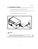
Страница 21: ...ect the connector of the power cord to the power inlet on the printe r 3 Insert the plug of the power cord in the AC outlet Use an AC outlet that accepts a three pronged plug Otherwise static electric...

Страница 22: ...power switches of the printer and the computer 2 Connect the connector of one end of the interface cable to the interface connector at the lower side of the printer and secure it with screws 3 Connect...

Страница 23: ...Before Operation 20 Chapter 2 Printer Operation 1 Power On Off 2 Normal Operating Mode 3 Printer Setup Mode 4 Self Test Mode 5 System Maintenance Mode 6 Returning to Factory Setting...

Страница 24: ...e printer 2 The green LED power indicator goes on Check that the LCD screen displays ON LINE When displaying an error message When operating normally When displaying no message Turn the LCD contrast a...

Страница 25: ...Before Operation 22 1 Power On Off Turning off the power 1 Turn off the power switch on the back of the printer 2 The green LED power indicator goes off and any message on the LCD screen disappears...

Страница 26: ...ing printing will stop after the current label is printed Press the Pause key again to resume printing Feed key FEED Advance to the top of the next label When using continuous paper make sure the Sens...

Страница 27: ...e Changing the paper gap sensor to the black line sensor 1 First check the printer goes ON LINE then press and hold the Pause key and then press the Feed key and release both keys 2 Change the print m...

Страница 28: ...ng mode with the Stop key Peeling sensor Auto cutter Tearing Sensor selection Transfer DirectTM PeelOFF PeelON CutOFF CutON TearOFF TearON Edge Reflect ContinuP Mode item Indication Edge Reflect Refle...

Страница 29: ...on When label paper is used Hold down the Feed key for two 2 seconds and the printer will feed the paper and print samples 1 and 2 and stop When continuous paper is used Hold down the Feed key for fo...

Страница 30: ...ng energy low Adjust printing energy Command Reference Partially blurred Head pressure unbalanced Adjust head pressure Section 2 Chapter 4 Ribbon wrinkling and slipping Ribbon tension improper Adjust...

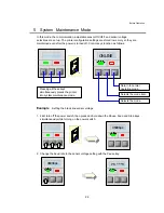
Страница 31: ...eys function as follows Example Setting the black line sensor voltage 1 First turn off the power switch then press and hold down the Pause Feed and Stop keys simultaneously while turning on the power...

Страница 32: ...ensor voltage with the Feed key 4 Return to normal operating mode with the Stop key Baud rate Data length Native 1 Adjustable sensor 3 Voltage setting 4 9600bps 19200bps 8bits 7bits NativeON NativeOF...

Страница 33: ...nsOF is changed to AJSensON and vice versa 5 Voltage setting In the voltage setting adjust the paper gap and black line adjustment controls so that the voltages of both PE and BL displayed on the LCD...

Страница 34: ...t tt ti in ng g Printer setup mode System maintenance mode Mode item Indication Mode item Indication Printing mode Transfer Baud rate 9600bps Peeling sensor PeelOFF Data length 8bits Auto cutter CutOF...

Страница 35: ...Before Operation 32...

Страница 36: ...r 3 Paper and Ribbon 33 Chapter 3 Paper and Ribbon 1 Kinds of Paper 2 Media Handling When Using Front Sensors 3 Media Handling When Using Adjustable Sensor 4 Paper Setting 5 Kinds of Ribbon 6 Ribbon S...

Страница 37: ...per must be high quality Otherwise good print quality and extended print head life cannot be guaranteed Type of paper Label paper continuous die cut fanfold Tag paper Ticket Both in wound and out woun...

Страница 38: ...lue mm in Maximum value mm in A Label width 0 3 4 65 B Liner width 1 0 4 65 C Label left edge position 0 10 D Label paper gap length 0 10 99 96 E Label length 0 10 99 96 F Label pitch 0 20 99 96 G Lin...

Страница 39: ...0049 Paper thickness 0 0025 0 01 Notch right end position 0 14 2 39 Notch left end position 2 25 Notch length 0 10 0 70 Black line right end position 0 59 2 62 Black line left end position 2 02 Black...

Страница 40: ...ttach the roll guide to the roll holder and insert this in the hole of the roll paper Set the roll holder with the roll paper and guide on the paper holder and push this against the left side wall so...

Страница 41: ...p left edge with the notch of the tearing plate 5 Slightly hold down the paper so as not to be skew and push down the open guide for closing 6 Push down the green tab on the front side until it clicks...

Страница 42: ...rt is pressed properly Otherwise the printer mechanism may fail to close 7 Close the printer cover 8 Turn on the power to the printer The LCD screen on the control panel will display ON LINE Press the...

Страница 43: ...set the print speed slower and the printing energy greater Type of ribbon Both in wound and out wound ribbons can be used With a single roll of ribbon 360 m about two rolls of paper with outer diamete...

Страница 44: ...to open the print head 2 Insert the ribbon shaft in the hole of the ribbon until it is in its deepest position 3 Set the ribbon holder on the transfer frame 4 Insert the ribbon shaft in the paper cor...

Страница 45: ...t on the front side until it clicks to securely close the printer mechanism Note Make certain the green part is pressed properly Otherwise the printer mechanism may fail to close 7 Close the printer c...

Страница 46: ...er 4 Printer Adjustments 1 Using Paper Other Than the Recommended Head Offset Adjustments 2 Using Narrow Paper Head Pressure Adjustments 3 Using Narrow Ribbon Ribbon Tension Adjustments 4 Adjustable S...

Страница 47: ...ise with a screwdriver Factory set Two turns Make fine adjustments checking the self test print b When using thick paper tag or other paper Peeping through the offset verification window adjust the he...

Страница 48: ...justments checking the print a When the print on right side is too light Move the mark to the right by turning the head pressure adjustment screw clockwise b When the print on the left side is too lig...

Страница 49: ...ch h r ri ib bb bo on n w wi id dt th h Knob on ribbon winding section Knob on ribbon feeding section Ribbon width 5 5 Adjustments when ribbon slipping occurs 4 4 25 4 mm 1 in 50 8 mm 2 in 3 3 76 2 mm...

Страница 50: ...he detection position align the scale marking on top of the upper guide rail with the sensor position mark yellow on the upper of the sensor The movable range of the adjustable sensor is shown below 2...

Страница 51: ...accessory cleaning pen or a soft cloth soaked in ethyl alcohol Cleaning of the thermal head is essential to guarantee print quality and extend print head life especially when printing on the direct th...

Страница 52: ...49 C Ch ha ap pt te er r 5 5 T Tr ro ou ub bl le es sh ho oo ot ti in ng g 1 Error Messages 2 Power Troubleshooting 3 Paper Feed Troubleshooting 4 Ribbon Feed Troubleshooting 5 Print Troubleshooting 6...

Страница 53: ...Communication error transmit buffer overflow HostBusy T D Full Blinks Sounds short 3 times Pause key pressed Pause Pause command reception remote control Pause Head overheat OverHeat Cooling Blinks So...

Страница 54: ...rinter Print density becomes low and print quality becomes inferior when the head temperature is low Head Err Head resistance value abnormal Check the contents and clear with the Stop key Replace the...

Страница 55: ...sm head PaperEnd Paper end paper out Install the paper PaperErr Paper out paper position cannot be detected Check the contents and clear with the Stop key Correct the faulty setting of the paper detec...

Страница 56: ...the problem cannot be resolved contact our service personnel OP Err Option board abnormal Turn off the power and reset the printer If this recurs contact our service personnel Cut Err Auto cutter abno...

Страница 57: ...nput voltage is greater or less than the rated voltage Correct RS 232C cable is not used Turn off the power switch and reconnect the power cord to the outlet properly Turn off the power switch and rec...

Страница 58: ...the paper See Chapter 3 Slightly push the roll guide to the roll paper See Chapter 3 Adjust it with the offset adjustment screw according to the width of the paper See Chapter 4 Paper doesn t align w...

Страница 59: ...erly See Chapter 3 Contact our service personnel Ribbon wrinkles Ribbon holder and winder tension is not correct Print density heating factor is not correct Angle of ribbon guide bar is not correct He...

Страница 60: ...eaning pen or a soft cloth soaked in ethyl alcohol etc See Chaper 4 Remove label ribbon or paper residue dust etc stuck to the platen See Chaper 4 Note If those cannot be removed contact our service p...

Страница 61: ...Chapter 3 Paper and Ribbon 58 Other printing abnormalities Check the error message on LCD screen and correct it according to the descriptions on Section 1 Error Messages Chapter 5...

Страница 62: ...auses Print disordered Error message is displayed and printer doesn t print Interface cable is not properly connected Interface cable is not the standard type Communication parameter setting is not co...

Страница 63: ...Appendixes 59 Appendixes 1 Options 2 Specifications...

Страница 64: ...f paper 25 4 118 mm 1 4 65 in Max diameter for roll paper 203 mm 8 in Inner diameter for roll paper 76 mm or more 3 in or more Min length of label 25 4 mm 1 in Thickness of paper Max 0 17 mm Max 0 006...

Страница 65: ...plications Storing downloaded fonts Downloaded HP Soft fonts can be stored Installation 1 Turn off the power to the printer 2 Remove the PCMCIA memory card cover at the bottom of the printer see figur...

Страница 66: ...ch mode Performs normal printing single or multiple sheets Peel mode Peels label from the liner after printing label Cut mode Prints and cuts by the specified number of sheets label back feeding enabl...

Страница 67: ...Appendixes 63 Paper core inner diam 25 4 mm 0 254 mm 1 in 0 01 in...

Страница 68: ...ptional Media detection sensors Paper top position home position adjustable with software Serial RS 232C Communication interface Parallel In conformity with Centronics LEDs Power and Error LCD Display...

Страница 69: ...0 EN 55022 class A EN 55024 Standards 230V system 220V 240V Europe EN 61000 3 2 61000 3 3 Operating conditions Temperature 5 35 C 41 95 F Humidity 30 80 non condensing Storage Temperature 20 60 C 68 1...

Страница 70: ...en the receive buffer reaches 2K bytes and resumes receiving data when the receive buffer reaches 4K bytes Baud rate 300 600 1200 2400 4800 9600 19200 38400 bps Bit length 7 or 8 bit Stop bit Fixed Wh...

Страница 71: ...2C loopback test After connector wiring as shown in the figure place the printer into self test mode The printer will receive data that has been transmitted by printer itself and the test of receiving...

Страница 72: ...has less than 2K bytes available Buffer in use Note Even if each code is ready for output the same code will not be transmitted twice successively except when the power is turned on or the printer is...

Страница 73: ...5 CTS Input RS 232C data transmission on computer enabled 6 NC Not connected 7 S GND Output Signal ground 8 NC Not connected 9 NC Not connected 10 NC Not connected 11 NC Not connected 12 NC Not connec...

Страница 74: ...Appendixes 70...

Страница 75: ...12 PERROR Output Signal specifying paper out 13 SELECT Output Signal specifying printer ON LINE printing enabled or OFF LINE pausing 14 AUTOFD Input Invalidness ignorance 15 NC Not used 16 S GND Outp...

Страница 76: ...ample of Connection to a Computer When RS 232C is used IBM PC compatible Communication control XON XOFF or CTS DTR PC DB25P 1 2 3 5 7 6 20 PRINTER DB25P 1 3 2 20 7 4 5 F GND TXD RXD CTS S GND DSR DTR...

Страница 77: ...to the manual tear position after printing The printer will feed back paper to the start print position when the next print job is sent If data is transmitted continuously from the computer the tear...

Страница 78: ...specified number of print sheets is completed Paper is fed to the tear position When manual tearing is needed tear the label at this time Performes next label printing When next print data is transmit...

Страница 79: ...key is pressed or next print data is transmitted from the computer the printer will feed back paper to the previous print completed position and resume feeding or printing 4 Priority order The follow...

Страница 80: ...off Parameter initialization values Initialization values of print and feed positions by each operating mode are described below unit mm in Normal printing Auto cutter Peeling Tear off Minimum value...

Страница 81: ...1 S Douglas Street Suite 121 El Segundo CA 90245 310 643 9825 U S A Citizen Systems Europe Ltd Mettinger Strasse 11 73728 Esslingen Germany 337 Bath Road Slough Berkshire SL1 5PR United Kingdom JE9950...

Отзывы: