Citizen CLP 621  CLP-621 CLP-621 Скачать руководство пользователя страница 27

27

Printer Operation

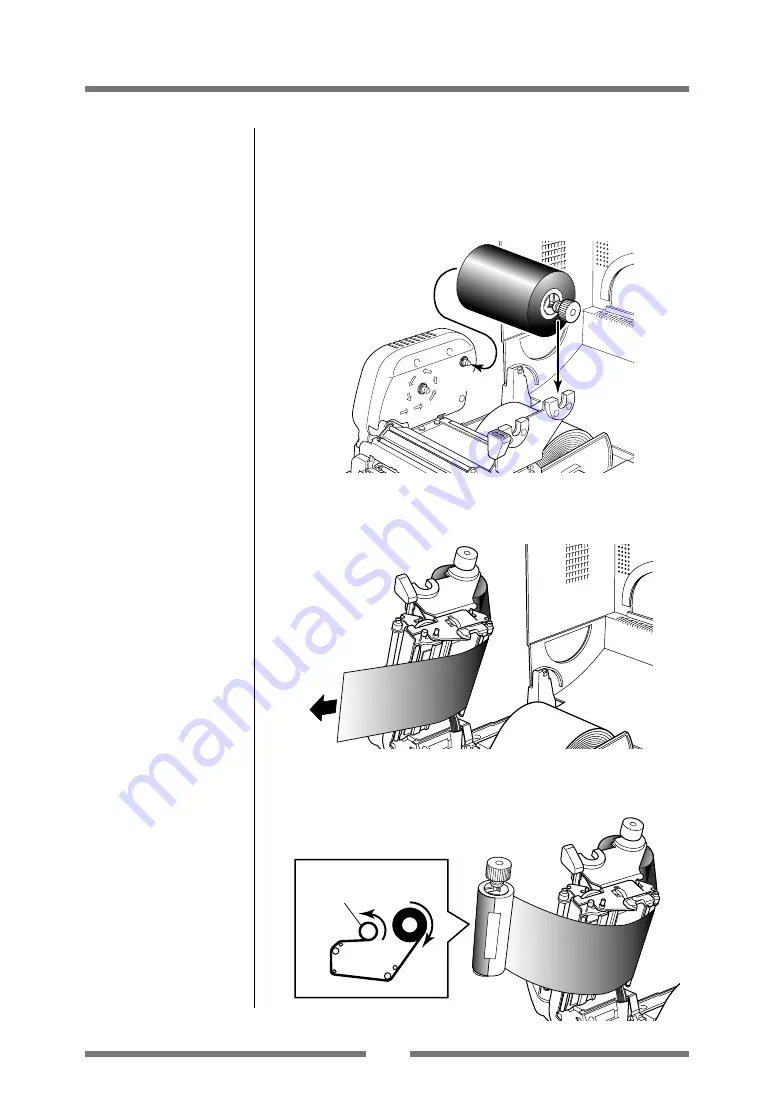
4. Push the large blue-head open lever to release the head unit.

Pull out the ribbon from the bottom of the head unit to the
ribbon winding side.

5. Using tape etc., fix the ribbon that you have pulled out on the

ribbon holder on which the paper core has been set and wind it
on the ribbon holder.

Winding side 
ribbon holder

Winding side 
ribbon holder

3. Install the unused ribbon and holder in to the rear ribbon drive

unit. The splines on the ribbon drive gear mechanism engage
with the end of the ribbon holder.

1

2

Setting the Ribbon

Содержание CLP 621 CLP-621 CLP-621

Страница 1: ...CLP 621 CLP 631 Thermal Transfer Barcode Label Printer USER S MANUAL...

Страница 2: ...Carton Contents 10 Part Names and Functions 1 1 Connection to Power 17 Driver Installation 17 Connection to a Computer 18 Chapter 2 Printer Operation Power ON OFF 19 Normal Operating Mode 20 Setting t...

Страница 3: ...r coded operator controls Interface A serial port IEEE1284 parallel port ECP mode and USB are standard equipment for quick data transfer and printing Optional interface The printers have optional inte...

Страница 4: ...pursuant to Part 15 of the FCC Rules These limits are designed to provide reasonable protection against harmful interference when the equipment is operated in a commercial environment This equipment...

Страница 5: ...to connect this device to computers Any changes or modifications not expressly approved by the grantee of this device could void the user s authority to operate the equipment ETAT DE CONFORMITE EMI A...

Страница 6: ...cord is used with this product make sure that the total of the ampere ratings on the products plugged into the extension cord do not exceed the extension cord ampere rating Also make sure that the tot...

Страница 7: ...ein Do not handle disassemble or repair the parts other than those specified in this manual We are not liable for any damage caused by user s erroneous use of the printer and inadequate environment Da...

Страница 8: ...air vent of the printer Do not place the printer where chemical reactions occur such as in laboratories or where air is mixed with salt or gas Do not use a power voltage or frequency other than those...

Страница 9: ...observe them Do not use or store the printer near fire excessive moisture in direct sunlight near an air conditioner or heater or other source of unusually high or low temperature or humidity or exces...

Страница 10: ...another strip of adhesive tape that must be removed which holds the mechanism closed for shipping Remove the tape and attached paper by carefully peeling from the plastic case Retain the tape should y...

Страница 11: ...n be checked through this window Be careful when moving or carrying the printer and when taking the printer out of the carton The printer may cause injury or property damage if dropped Be sure to grip...

Страница 12: ...the ribbon When you remove the label you should see ink on the adhesive label if the label was touching the inked surface 2 Ribbon drive unit 3 Head close knob Push the head close knob to lock the mec...

Страница 13: ...nt knob This is adjusted according to the width of the ribbon that is used Use it basically in the same way as the front adjustment knob 5 Back feeding side ribbon left right balance adjustment knob I...

Страница 14: ...des Left fixed media guide 4 1 and right movable media guide 4 2 The end of the media is matched to the left fixed media guide then the right side movable media guide is moved horizontally to match it...

Страница 15: ...orange 4 ERROR LED This is lit or flashes when the printer is in an alarm or error status red 5 PAUSE key This temporarily stops printing 6 FEED key This key feeds the media to the top of the next la...

Страница 16: ...EEE1284 This receives parallel transmission of data from a host computer 3 USB interface This receives USB transmission of data from a host computer 4 Power switch The is the power switch for the prin...

Страница 17: ...ted and there will be danger of electric shock AC Outlet Power Cord Inlet Power Switch Driver Installation The computer may automatically detect the presence of the new printer when it is first starte...

Страница 18: ...terface cable to the interface connector on the back of the printer and secure it with locks or locking screws where available 3 Connect the other end of the interface cable to the interface connector...

Страница 19: ...Turn on the power switch on the back of the printer 2 The POWER and PRINT LED are lit Turning off the power 1 Turn off the power switch on the back of the printer 2 The POWER and PRINT LED go off Powe...

Страница 20: ...position then it is cut Regardless of whether there is or is not a cut operation setting on the setting menu if the unit is installed the media is cut each time it is fed If the optional peeler unit...

Страница 21: ...2 3 4 ON OFF ON OFF ON OFF ON OFF ON OFF ON OFF ON OFF ON OFF ON OFF ON OFF Auto cutter abnormality jamming etc PRINT LED ERROR LED CONDITION LED When the STOP key has been pushed OFF OFF OFF OFF OFF...

Страница 22: ...lack mark detection Transparent sensor Continuous media Label Label Label Printed area Reflective sensor Media direction Label media Menu Setting Table p 36 Min value mm inches Max value mm inches A L...

Страница 23: ...ce of the media guide touching the roll Installing the Media 1 Push the large blue head open lever to release the head unit and then lift the sensor arm by hand as shown below Media Sizes p 22 Setting...

Страница 24: ...ue head open lever side Movable media guide Upper sensor Bottom sensor Transparent sensor marker Upper sensor marker Front Aligned with the marker Platen When using a reflective sensor Adjust the posi...

Страница 25: ...e head unit Align it with the width of the media that has been set then set the media width and media thickness adjustment dials See Chapter 3 Printer Adjustments Head close knob Media width adjustmen...

Страница 26: ...d of ribbon used and set the ribbon winding selection switch This is the method for installing an outside wound ribbon This switch allows selection of inside wound ribbons also known as ink in and out...

Страница 27: ...pe etc fix the ribbon that you have pulled out on the ribbon holder on which the paper core has been set and wind it on the ribbon holder Winding side ribbon holder Winding side ribbon holder 3 Instal...

Страница 28: ...o not disappear or if it slips perform ribbon balance adjustment and ribbon tension adjustment See Chapter 3 Printer Adjustments for these adjustment methods Head close knob 6 Set the ribbon holder on...

Страница 29: ...e PRINT LED has begun to flash slowly release the STOP key and then the printer enters HEX DUMP mode When using continuous media Turn on printer power while pushing the STOP key If the PRINT LED has s...

Страница 30: ...prints then printing stops To restart printing press the FEED key once more Setting the Media P 22 Mode Settings Media Adjustments Using the Self Test Print shown above you can make adjustments to th...

Страница 31: ...lect the current menu option or to save the new setting after which it advances to the next menu STOP key NO Next Item Change Value Whilst changing a menu value such as head temperature pressing this...

Страница 32: ...up Menu items Do you want to change System Setup Menu items Do you want to change After Print Menu items Do you want to change Interface Menu items Initialization of the content of the settings Initia...

Страница 33: ...Shift Media Sensor Small Media Adjustment Sensor Level Buzzer Select Metric Inch Max Media Length Settings Lock Keyboard Lock Control Code DMX Mode Only Emulation Select AutoConfigure Function Select...

Страница 34: ...ng the print speed and print darkness then continues through the remainder of the Print Setup menu The actual output from the printer is vertically reversed due to the way the printer outputs the menu...

Страница 35: ...Flow Chart p 32 Mode Settings Note Citizen continually enhances its printers with new options and settings based on our customer s requests Extra or changed menu items may appear on the above print ou...

Страница 36: ...0 0mm 25 4 to 25 4mm Media Sensor See Through See Through Label sensor selection Reflect None Small Media OFF ON Setting for small labels Adjustment OFF Small Media 1 00 IN 0 25 to 1 00 IN Setting len...

Страница 37: ...The general stop position 0 0 to 50 8mm is selected depending on the Function Peel Cut Tear On selected above 1 00 to 1 00 IN 25 4 to 25 4mm Mode Repeat Key Disabled LabelSet Repeat method selection...

Страница 38: ...printer switches between thermal transfer method and direct thermal method If thermal transfer method has been selected the buzzer sounds once and the CONDITION LED flashes If direct thermal method ha...

Страница 39: ...ly Power Switch 2 After the PRINT LED and CONDITION LED light up release the keys to change the printer to sensor adjustment setting mode Quick Sensor Selection Method Transparent Reflective To switch...

Страница 40: ...sparent sensor and open the sensor arm 3 Install only the liner media label backing paper with the label media removed so that it will pass between the platen roller and the media sensor Be careful th...

Страница 41: ...shing media feeding starts and the sensor is automatically adjusted 5 If automatic adjustment stops normally the PRINT LED and CONDITION LED return to their original status If it does not stop normall...

Страница 42: ...n the dial to the largest number on the dial one step at a time When using thicker media tags card etc Adjust while performing test printing by turning the dial from the smallest number on the dial to...

Страница 43: ...nt dial If the printing is blurred or lightly printed on one side or the media moves in a zigzag pattern adjust the head pressure balance After making an adjustment confirm the output quality with a t...

Страница 44: ...on tension has three adjustment positions on both the feeding side back side and winding side front side Weak Strong Strong Weak Front Back Adjustment criteria Ribbon width of 4 inches strong Ribbon w...

Страница 45: ...int to ensure that the ribbon is not wrinkled If it is wrinkled turn the back adjustment knob to the right and do the test printing again and check to make sure that the ribbon is not wrinkled Case of...

Страница 46: ...eriods which will guarantee the print quality and extend the life of the thermal printhead Note Always use the head cleaner when cleaning the thermal printhead Head cleaner Thermal printhead Caution D...

Страница 47: ...or a ribbon of the same type 1 Correctly set the media and the ribbon 2 Set the appropriate printing density using the menu or control software 3 If it is dirty clean it with ethyl alcohol If it is d...

Страница 48: ...l material is stuck to the print head remove it with a soft cloth soaked in ethyl alcohol 5 Use the recommended ribbon or a ribbon of the same type 6 Adjust the offset of the thermal printhead with th...

Страница 49: ...ut position After cutting printing restarts but a gap may be created at the seam of the printing at this time Peel mode 2 Peels labels from the liners after printing them Media Types of media Roll fan...

Страница 50: ...o Datamax programming language 6 Outline of electronic CPU 32Bit RISC CPU devices ROM Standard equipment FLASH ROM 2Mbyte RAM Standard equipment SDRAM 8MByte Media detection Transparent sensor Detects...

Страница 51: ...Options can be separately purchased 3 When a media pitch of less than 1 inch is used activate the Small Label Printing setting in the Printing Setting 4 The OCR font may have a low recognition rate a...

Страница 52: ...pecifications Pin No Signal code Signal name Function 1 FG Protective Protective grounding grounding 2 TXD Transmitted data Signal line that transmits data from the printer to other devices 3 RXD Rece...

Страница 53: ...n 128 bytes available 16Kbyte XON XOFF Receive buffer 1024 byte 128byte DTR Protocol Conditions when the DTR signal is Ready High All the following conditions are satisfied The receive buffer is 128 b...

Страница 54: ...bi directional asynchronous data transmission and thanks to its interlock handshake it does not require the timing necessary with compatible mode Signal level IEEE1284 standard Pin No Signal name I O...

Страница 55: ...or Busy Receive buffer full Data being read Error Parallel port status signals when an error occurs The status of a signal line will not be changed in bi directional mode such as nibble or ECP mode Co...

Страница 56: ...hile receiving INIT signal Note If the Init signal does not have width of 10 to 15 sec or more it cannot act as an Init signal If it is lower the Init signal is ignored BUSY starts up when the Init si...

Страница 57: ...n Transmission speed Compatible with 12Mbps full speed transmission Receive buffer 16kB Connector DUSB DUSB BRA42 T1 1 DDK Pin No Signal code Signal Function 1 VBUS USB power USB power 5V 2 D Signal l...

Страница 58: ...cting cable and do not pull the cable too much If you do it will cause a malfunction Always turn off the power to the printer before replacing the interface board Do not pull it out with unnecessary f...

Страница 59: ...t the interface board into the printer so that the connecting cable does not catch on the printer then use the screws 2 that you removed to anchor the bracket Rear Side Interface Board Screw Replacing...

Страница 60: ...e 11 Park House 643 651 Staines Road D 73728 Esslingen Feltham Middlesex TW14 8PA Germany United Kingdom Tel 49 0 711 3906 420 Tel 44 0 20 8893 1900 Fax 49 0 711 3906 405 Fax 44 0 20 8893 0080 http ww...

Отзывы: