Chapter 2 Operating Principles
2-2.
Operation of Control Parts
2-35
CL-E700 series
(3)
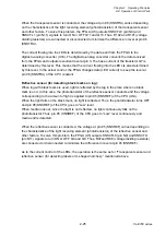
Head driver
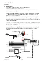
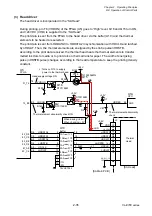
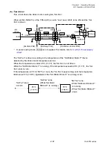
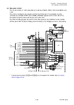
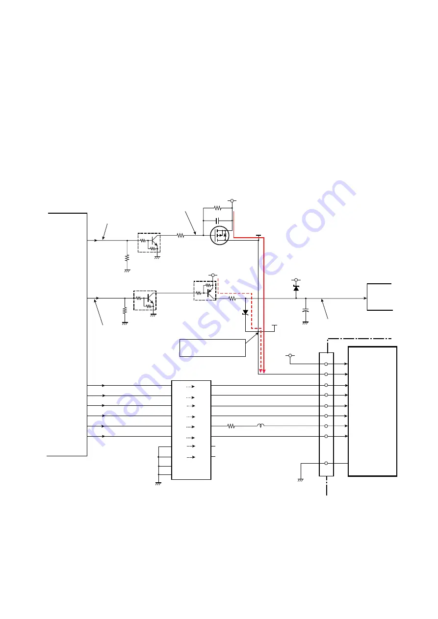
The head driver is incorporated in the “SA Head”.
During printing, pin T6 (VHDON) of the FPGA (U5) goes to “High” level, Q16 and Q15 turn ON,
and +24V DC (VHD) is supplied to the “SA Head”.
The print data is sent from the FPGA to the head driver via the buffer (U10) and the thermal
elements to be heated are selected.
The print data is sent from HDDATA0 to HDDATA2 in synchronization with HDCLK and latched
by nHDLAT. Then, the thermal elements are energized by the strobe pulse nHDSTB.
According to the print data received, the thermal head heats the thermal elements to transfer
melted ink dots to media or to print dots on thermal transfer paper. The width of energizing
pulse (nHDSTB pulse) changes according to the head temperature to keep the printing density
constant.
J2
Thermal
Head
1-4,23-26
nHDSTB
HDCLK
HDDAT1
nHDLAT
+5.0V
16
18
13
81_A8
A8
83_C6
C6
VHCON
31_T6
T6
15_E5
E5
Q2
DTC114EM
D2
CPU
D1
+3.3V
Head supply voltage ON
Thermal element abnormality check ON
Thermal element abnormality
check
When driving: +24V
When checking: +5V
nHDSTB
HDCLK
nHDLAT
1
19
/1G
/2G
74VHCT244
2A1
2A2
2A3
2A4
1A1
1A2
1A3
1A4
Buffer
84_D6
D6
83_C8
C8
82_B8
B8
84_D8
D8
HDDATA2
HDDATA1
HDDATA0
2Y1
2Y2
2Y3
2Y4
1Y1
1Y2
1Y3
1Y4
5,6,8,11,12,
19,20,22
HDDAT2
HDDAT3
7,9,15
11
13
15
17
2
4
6
8
9
7
5
3
18
16
14
12
R53
L1
C87
VHD
Q1
DTA114EM
+5.0V
R52
R163
Q16
DTC114EM
Q15
TJ100F06M3L
L: Turns on Q15 to supply
power to the thermal head.
R132
VHDON
+24V
R127
R129
C148
U10
FPGA
U5
[SA Main PCB]
VHD
U1A
[SA Head]
VDD
HDRES
AN0
94
VHD
17
14
10
Содержание CL-E700 Series
Страница 1: ...Technical Manual CL E700 series Thermal Transfer Printer...
Страница 5: ...Chapter 1 Specifications 1 1 CL E700 series CHAPTER 1 SPECIFICATIONS...
Страница 15: ...Chapter 2 Operating Principles 2 1 CL E700 series CHAPTER 2 OPERATING PRINCIPLES...
Страница 87: ...Chapter 3 Disassembly and Maintenance 3 1 CL E700 series CHAPTER 3 DISASSEMBLY AND MAINTENANCE...
Страница 151: ...Chapter 4 Troubleshooting 4 1 CL E700 series CHAPTER 4 TROUBLESHOOTING...
Страница 167: ...Chapter 5 Parts Lists CL E700 series CHAPTER 5 PARTS LISTS...
Страница 172: ...Chapter 5 Parts Lists CL E700 series 5 6 DRAWING NO 1 General Assembly Rev 0...
Страница 195: ...Chapter 5 Parts Lists 5 29 CL E700 series DRAWING NO 7 Unit Opepane Rev 0...
Страница 203: ...Chapter 5 Parts Lists 5 37 CL E700 series DRAWING NO 9 SA2 Ribbon Unit Fan Rev 0...
Страница 206: ...Chapter 5 Parts Lists CL E700 series 5 40 DRAWING NO 10 Accessories Rev 0 3 2 4 1 1 1 2 1 3...
Страница 208: ...Chapter 6 Circuit Diagrams 6 1 CL E700 series CHAPTER 6 CIRCUIT DIAGRAMS...
Страница 230: ...Appendices AP 1 CL E700 series APPENDICES...
Страница 232: ...Appendices A Mounting Diagrams AP 3 CL E700 series A Mounting Diagrams A 1 SA Main PCB 1 Parts side...
Страница 233: ...Appendices A Mounting Diagrams CL E700 series AP 4 2 Solder side...

