background image


19

Installing the Cisco WAE Inline Network Adapter

OL-12480-03

  Installing Adapters in the WAE-7326 Appliance

Installing an Inline Network Adapter

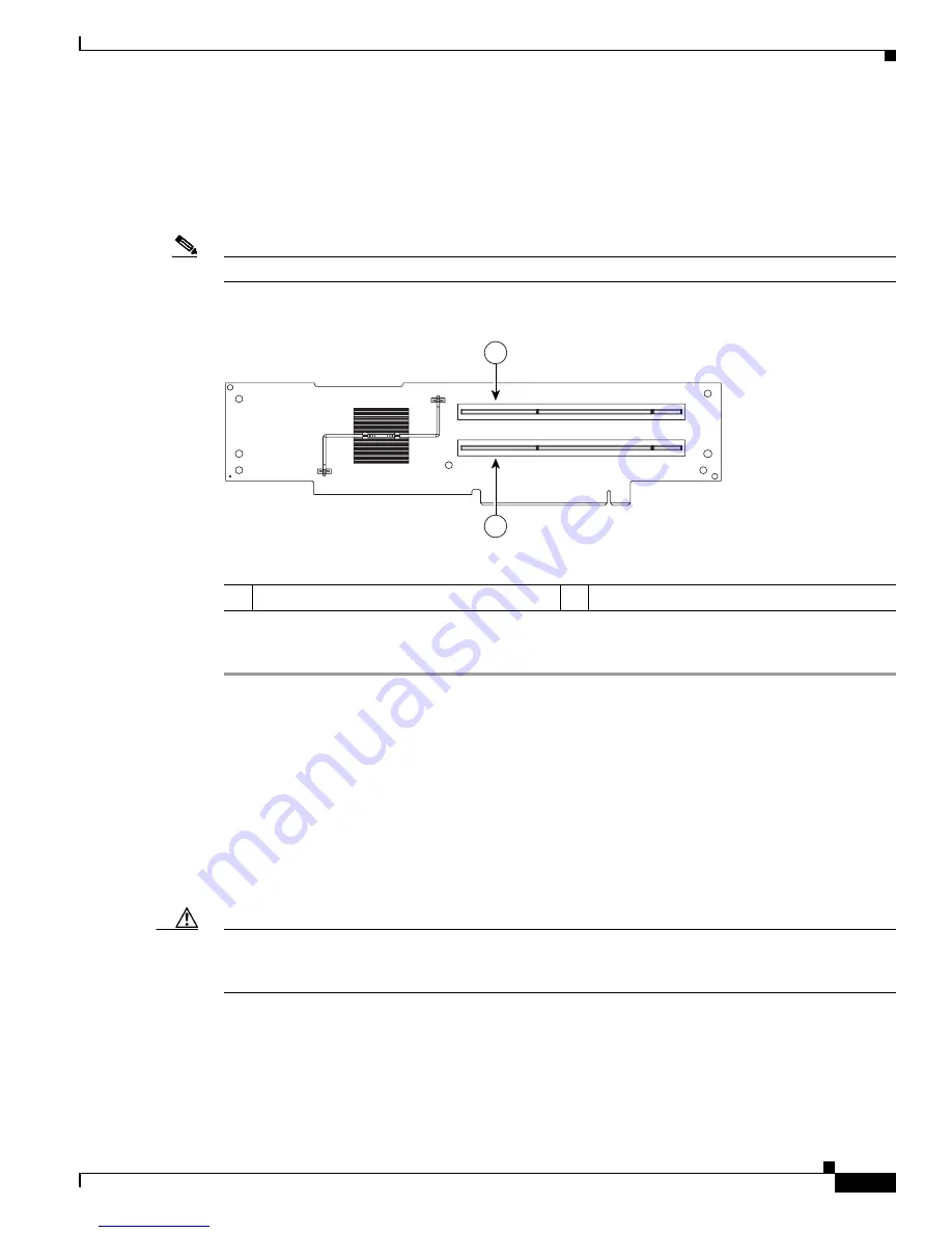
The WAE-7326 has connectors for up to four PCI adapters on the system board and PCI riser card. You 
can install the inline network adapter in slot 3 (labeled 1 in 

Figure 12

) or in slot 4 (labeled 2 

Figure 12

in on the PCI riser card.

Note

The PCI riser card is located at J73 on the system board.

Figure 12

PCI-X Riser Card

To install an inline network adapter, follow these steps:

Step 1

Review the information in the 

“Safety Guidelines” section on page 5

.

Step 2

Power down the device and peripheral devices and disconnect all power cords and external cables.

Step 3

Remove the cover. (See the 

“Removing the Cover” section on page 18

.)

Step 4

Remove the PCI riser card assembly. 

Step 5

Slide the expansion-slot cover out of the PCI riser card cage.

Step 6

Touch the static-protective package that contains the adapter to any unpainted metal surface on the 
device, and then remove the adapter from the static-protective package. Avoid touching the components 
and gold-plated edge connectors on the adapter.

Step 7

Place the adapter, component-side up, on a flat, static-protective surface.

Caution

When you install an adapter in the device, be sure that it is completely and correctly seated in the PCI 
expansion slot before you power up the device. Incomplete insertion might cause damage to the system 
board or the adapter.

Step 8

To install the adapter, carefully grasp the adapter by its top edge or upper corners, align it with the 
expansion slot in the riser card assembly, and then press the adapter 

firmly

 into the expansion slot. 

Step 9

Reinstall the riser card. Make sure that the riser card is fully seated in the riser card connectors on the 
system board. 

Step 10

Connect any needed cables to the adapter. 

1

PCI-X slot 3, 64 bit 3.3 V 133 MHz (PCI 3)

2

PCI-X slot 4, 64 bit 3.3 V 133 MHz (PCI 4)

137707

1

2

Get user manuals: 

See SafeManuals.com


Содержание WAE-INLN-4CG Series

Страница 1: ...erienced technicians Note The Cisco WAE inline network adapter is not supported in a Central Manager appliance For more information see the Important Operational Notes section on page 7 Contents This document contains the following sections Product Overview Safety Guidelines Important Operational Notes Installing Adapters in the FE 511 WAE 511 and WAE 611 Appliances Installing Adapters in the WAE ...

Страница 2: ...TRUCTIONS Product Overview This section contains the following topics Inline Network Adapter Description Ports and LED Indicators Adapter Specifications Note The minimum software release required for the inline network adapter is WAAS 4 0 7 Inline Network Adapter Description WAAS software versions prior to 4 2 1 support one optional 4 port Ethernet inline network adapter on WAE 7341 WAE 7371 WAE 6...

Страница 3: ...t group lan or slot group wan The last attribute is the LAN or WAN designator The inline network adapter also includes an onboard programmable watch dog timer WDT controller that allows you to set the time to wait after a failure event such as a power outage or a kernel crash before the unit begins to operate in mechanical bypass mode In mechanical bypass mode traffic is bridged between the LAN an...

Страница 4: ...ine Network Adapter Specifications Specification Description Copper Gigabit Ethernet Specifications IEEE standard Gigabit Ethernet 1000BASE T Fast Ethernet 100BASE T Ethernet 10BASE T Full duplex and half duplex Supports both half duplex and full duplex operation in all operating speeds Autonegotiation Autonegotiates between full duplex and half duplex operations and between 1000 Mbps 100 Mbps and...

Страница 5: ...and pose a risk of fire and electrical hazards Statement 117 Warning Blank faceplates filler panels serve three important functions they prevent exposure to hazardous voltages and currents inside the chassis they contain electromagnetic interference EMI that might disrupt other equipment and they direct the flow of cooling air through the chassis Do not operate the system unless all cards and face...

Страница 6: ...ect external power source Operate the product only from the type of power source indicated on the electrical ratings label If you are not sure of the type of power source required consult your service representative or local power company Use only approved power cables If you have not been provided with a power cable for your Content Engine or for any AC powered option intended for your system pur...

Страница 7: ...down place it in its static protective package Do not place the adapter on your system unit cover or on a metal table Handle all sensitive components in a static safe area If possible use antistatic floor pads and workbench pads Handle the adapter carefully holding it by its edges or its frame Do not touch solder joints pins or exposed printed circuitry Do not leave the adapter where others can ha...

Страница 8: ...section on page 5 Step 2 Power down the appliance and all attached devices Disconnect the power cord and all external cables Step 3 Loosen the two captive screws labeled 1 in Figure 3 on the rear of the cover Figure 3 Removing the Cover Step 4 Slide the cover back and then lift it up and off the appliance Caution For proper cooling and airflow replace the cover before turning on the appliance Oper...

Страница 9: ...ons to avoid damage from static electricity For details on handling these devices see the Protecting Against Electrostatic Discharge section on page 7 Note The illustrations in this document might differ slightly from your hardware To install an inline network adapter follow these steps Step 1 Review the safety information in the Safety Guidelines section on page 5 Step 2 Power down the appliance ...

Страница 10: ...AE 611 Appliances Figure 4 Removing the Expansion Slot Cover Step 6 Remove the riser card labeled 1 in Figure 5 from the system board to access the expansion slot 1 Expansion slot cover slot 2 2 Expansion slot cover slot 1 3 Captive screw 4 Riser card assembly 1 2 4 3 124478 Get user manuals See SafeManuals com ...

Страница 11: ...e and set any jumpers or switches as described by the adapter manufacturer if necessary Caution When you install an adapter in the appliance be sure that it is completely and correctly seated in the PCI expansion slot before you power up the appliance Incomplete insertion might cause damage to the system board or the adapter Step 9 To install the adapter carefully grasp the adapter by its top edge...

Страница 12: ...t all cables that you disconnected earlier Caution To maintain proper cooling and airflow install the cover before turning on the appliance Operating the appliance for extended periods over 30 minutes with the cover removed might damage internal components To install the cover follow these steps Step 1 Install the cover by placing it into position and sliding it forward and then tighten the captiv...

Страница 13: ...on Removing the Cover Warning Before working on a chassis or working near power supplies unplug the power cord on AC units Statement 246 To remove the cover follow these steps Step 1 Review the information in the Safety Guidelines section on page 5 Step 2 Power down the device and all attached devices Disconnect the power cord and all external cables Step 3 Press the cover release button labeled 1...

Страница 14: ...slot 2 is for one low profile half length adapter however it is not used in this device You must install supported adapters in PCI X slot 1 This slot is labeled Slot 1 on the back of the device Caution When you handle static sensitive devices take precautions to avoid damage from static electricity For details on handling these devices see the Protecting Against Electrostatic Discharge section on ...

Страница 15: ... a flat static protective surface Step 7 Remove the expansion slot cover for Slot 1 See Figure 9 Note You must install PCI expansion slot covers on all vacant slots so that you can maintain the electronic emissions characteristics of the appliance and ensure proper cooling of internal components 1 Riser card assembly 2 Rear edge of riser card 151927 1 2 Front Rear Get user manuals See SafeManuals ...

Страница 16: ... device be sure that it is completely and correctly seated in the PCI expansion slot before you power up the device Incomplete insertion might cause damage to the system board or the adapter Step 10 To install the adapter carefully grasp the adapter by its top edge or upper corners align it with the expansion slot in the riser card assembly and then press the adapter firmly into the expansion slot...

Страница 17: ... placing it into position and sliding it forward See Figure 10 Figure 10 Installing the Cover Caution Before sliding the cover forward make sure that the cover will properly engage the ledge at the front of the device Step 2 Install the device in the rack Step 3 Connect all external cables and the power cord to the device and then plug the power cord into a properly grounded electrical outlet Inst...

Страница 18: ...external cables and power cords Step 3 Press down on the left and right side latches and pull the device out of the rack enclosure until both slide rails lock Note You can reach the cables on the back of the device when the device is in the locked position Step 4 Lift the cover release latch labeled 1 in Figure 11 Lift the cover off the device and set the cover aside Figure 11 Removing the Cover C...

Страница 19: ...ep 6 Touch the static protective package that contains the adapter to any unpainted metal surface on the device and then remove the adapter from the static protective package Avoid touching the components and gold plated edge connectors on the adapter Step 7 Place the adapter component side up on a flat static protective surface Caution When you install an adapter in the device be sure that it is ...

Страница 20: ...ution When you route cables do not block any connectors or the ventilated space around any of the fans Make sure that cables are not routed on top of components under the PCI riser card assembly Make sure that cables are not pinched by the server components Note Remove the fan guide before you route the cables Reinstall the fan guide when you complete the cable routing 1 Riser card cage 2 SCSI cab...

Страница 21: ...th the cover removed might damage internal components To install the cover follow these steps Step 1 Place the cover release latch labeled 1 in Figure 14 in the open up position Step 2 Insert the bottom tabs of the top cover into the matching slots in the device chassis Step 3 Press down on the cover release latch to lock the cover in place Figure 14 Installing the Cover Step 4 Install the applian...

Страница 22: ...n off switch turn OFF the power and unplug the power cord Statement 1 To remove the device top cover follow these steps Step 1 Review the information in the Safety Guidelines section on page 5 Step 2 Power off the device and all attached devices and disconnect all external cables and power cords Step 3 Press down on both side latches and pull the device out of the rack enclosure until both slide r...

Страница 23: ...rmation in the Safety Guidelines section on page 5 Step 2 Power down the device and peripheral devices and disconnect all power cords and external cables Step 3 Remove the cover See the Removing the Cover section on page 22 Step 4 Remove the PCI X riser card assembly See Figure 16 Push the two riser card assembly release tabs toward the PCI X slots Grasp the assembly at the rear and side edges and...

Страница 24: ...any connectors or the ventilated space around any of the fans Make sure that cables are not routed on top of components under the PCI X riser card assembly Make sure that cables are not pinched by the device components Step 9 Carefully align the riser card assembly with the release tab posts the guides on the rear of the WAE and the riser card connector on the system board Press down on the assemb...

Страница 25: ...s Figure 18 Installing the PCI X Riser Card Assembly Step 10 Perform any configuration tasks required for the adapter Step 11 Reinstall the cover For instructions on completing the installation see the Completing the Installation section on page 26 Access holes Release tabs Guide Guide 185092 Get user manuals See SafeManuals com ...

Страница 26: ...dapter ships with two types of cables crossover and straight through When you connect the WAE inline network adapter the cable that you use depends on the link speed Gigabit Ethernet or Fast Ethernet and the types of devices DCE or DTE being connected Note You must retain the same link speed from one end of the connection to the other end Inline adapter interfaces are able to autonegotiate link sp...

Страница 27: ...d the WAN sides of the WAE inline appliance you must consider the types of devices that are being connected and you must use the correct cables You must follow these cabling instructions for the inline network adapter to work properly See Table 4 For illustrations and examples see the Installation Scenarios and Cabling Examples for Fast Ethernet Connections section on page 29 To connect the inline...

Страница 28: ...rent from the cable that you would use to connect the two network devices directly as determined in Step 1 For example if you are connecting a router and a switch two different devices through the WAE inline appliance use a straight through cable on the LAN side of the connection and use a crossover cable on the WAN side of the connection If you were connecting the two different devices directly y...

Страница 29: ... redundant WAN links See Figure 20 Two WAEs with inline network adapters can also be installed back to back in a serial fashion between two network devices for failover purposes In this serial cluster configuration if one WAE fails the other WAE can provide optimization See Figure 21 Note When you connect two WAE inline appliances to each other serially always use a crossover cable between the two...

Страница 30: ...o WAN router Fast Ethernet WAE 2 WAN0 InlinePort 1 0 wan Cable type Crossover MGMT 240088 WAE1 WAN Router B WAE2 LAN switch 3 1 2 1 Connection WAE 1 to LAN switch Fast Ethernet WAE 1 LAN0 InlinePort 1 0 lan Cable type Straight through 2 Connection WAE 1 to WAE 2 Fast Ethernet WAE 1 WAN0 InlinePort 1 0 wan to WAE 2 LAN0 InlinePort 1 0 lan Cable type Crossover 3 Connection WAE 2 to WAN router Fast E...

Страница 31: ...formation on obtaining documentation obtaining support providing documentation feedback security guidelines and also recommended aliases and general Cisco documents see the monthly What s New in Cisco Product Documentation which also lists all new and revised Cisco technical documentation at http www cisco com en US docs general whatsnew whatsnew html This document is to be used in conjunction wit...

Страница 32: ...32 Installing the Cisco WAE Inline Network Adapter OL 12480 03 Obtaining Documentation Obtaining Support and Security Guidelines Get user manuals See SafeManuals com ...

Отзывы: