background image

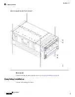
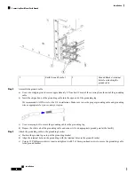
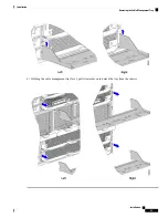
Figure 22: Securing the Front of the Chassis to the Rack

Step 5

Choose the appropriate option:

a) If your chassis will ship pre-installed in a rack, attach the rear mounting brackets. If you plan to install and ship your

chassis in a shippable rack, attach the rear mounting brackets. See

Installing Rear Mounting Brackets, Round-Hole

Rack, on page 42

.

b) If you will be installing the chassis in a stationary rack, continue the installation procedure. See

Completing Installation,

on page 44

.

Installing Rear Mounting Brackets, Square-Hole Rack

Use this procedure to install the rear mounting (tie down) brackets (UCSX-9508-RACKBK) for a chassis that
is not pre-installed in a rack.

Installation

40

Installation

Installing Rear Mounting Brackets, Square-Hole Rack

Содержание UCS X9508

Страница 1: ...Information for Cisco UCS for important safety information Note IMPORTANT SAFETY INSTRUCTIONS This warning symbol means danger You are in a situation that could cause bodily injury Before you work on any equipment be aware of the hazards involved with electrical circuitry and be familiar with standard practices for preventing accidents Use the statement number provided at the end of each warning t...

Страница 2: ...EIA 310 D E compliant rack Your equipment racks must also be compliant with EIA 310 D E standard The Cisco UCS X9508 chassis can be installed in either a 9 5 mm square hole rack or a 7 1 mm unthreaded round hole rack These racks require either square hole cage nuts or round hole cage nuts also called spring nuts respectively Cage nuts and spring nuts are not provided by Cisco They should have acco...

Страница 3: ...the hot air generated by equipment at the bottom of the rack can be drawn in the intake of the equipment above Make sure that the exhaust at the rear of the chassis is unobstructed for at least 24 in 61 cm This includes obstruction due to messy cabling practices If an enclosed rack is used the front door must be 65 percent perforated to ensure adequate airflow to the compute nodes Earth Ground Con...

Страница 4: ...mple shown below The positive and negative wires can be installed pointing either to the right or to the left as long as the terminal cover is used Panduit LCD4 14A L connectors or equivalent may be used supply and return wires and Panduit LCD4 14A or equivalent connectors may be used for the 90 degree ground lug wire Both connections have double lugs with 25 inch holes measuring 625 inches from c...

Страница 5: ...Use the following grasp points when handling the chassis Front grasp points horizontal Installation 5 Installation Handling the Chassis ...

Страница 6: ... Rear grasp points Do not lift or handle the chassis by the top rear sheet metal as indicated by the DO NOT LIFT label on the top rear surface Note Installation 6 Installation Handling the Chassis ...

Страница 7: ...he information listed in Site Planning and Maintenance Records as you install and configure the chassis Ensure that there is adequate space around the chassis to allow for servicing the chassis and for airflow Ensure that the air conditioning meets the heat dissipation requirements listed in Technical Specifications Ensure that the cabinet or rack meets the requirements listed in Rack Requirements...

Страница 8: ...p the shipping container in case the chassis requires shipping in the future Tip The chassis is thoroughly inspected before shipment If any damage occurred during transportation or any items are missing contact your customer service representative immediately Note As part of this procedure you will be moving an empty chassis out of the shipping container Be aware of the following precautions You w...

Страница 9: ...M6 cage nut 4 M6 x 20mmL screw 16 Power Cable Management Arm 2 UCSX 9508 PCMA ESD Strap Clip Terminated Rail Kit UCSX 9508 RAIL1 Any printed documentation Any optional items which will be present in the accessory kit only if you ordered them with your system Rear Mounting Brackets 1 left bracket 1 right bracket UCSX 9508 RACKBK These brackets are optional They should be ordered only if you plan to...

Страница 10: ...Step 8 Using a 13 millimeter socket driver remove the four M8 hex head securing bolts two per side Save the securing bolts Note Installation 10 Installation Unpacking and Inspecting the Chassis ...

Страница 11: ...lift or scissor jack that can support the chassis weight Step 10 Before installing the chassis into an equipment rack use a 2 Phillips screwdriver to remove the two M5 screws two per handle that secure the handles to the chassis Save the handles and screws Note Installation 11 Installation Unpacking and Inspecting the Chassis ...

Страница 12: ... nuts rail kit locator pegs and screws should be installed The templates facilitate installing the rail kit and chassis by ensuring proper spacing and alignment of installation hardware in both the left and right sides of the rack The chassis has one template for the front of the rack and one for the back Rail installation templates are applicable to either square hole or round hole equipment rack...

Страница 13: ... and install the cage nuts and other hardware as shown Figure 1 Rack Installation Template Front Rear Install Template Use this installation to locate the correct spacing and alignment for chassis mounting hardware on the rack This template shows the rack locations for mounting the rear of the chassis Align the Chassis Top of the template with the location in the rack where the top of the chassis ...

Страница 14: ...nt racks that have either square or round holes For more information see Rack Requirements on page 2 The X9508 server is supported on a rail kit which mounts to the square hole or round hole cage For untapped equipment racks you must install cage nuts to provide a way for mounting screws to secure rails and the chassis to the rack Caution Use the appropriate option depending on your type of equipm...

Страница 15: ... that they are easy to use To use the rack installation templates go to the appropriate topic Front Install Template on page 13 Rear Install Template on page 13 Step 1 Gather the M6 cage nuts and a flat head screwdriver Step 2 Locate the template and refer to the chassis location in the rack and the cage nut locations on the template Step 3 Position one of the curled sides of the cage nut on the i...

Страница 16: ...ur equipment rack Before you begin This document provides illustrations of installation templates for the front and rear of the chassis The templates are designed to show you the proper holes within which the rails and cage nuts spring nuts should be placed Once you align the rack holes line up with the template you should mark the holes on the rack so that they are easy to use To use the rack ins...

Страница 17: ...es up with the round hole in the equipment rack Cage nuts install so that most of the nut is behind the rack s sheet metal Note If needed use the flat head screwdriver to slightly pry open the gap between the spring nut s sheetmetal to allow it to slide onto the rack over the round hole Note Step 5 Verify that the cage nut is fully and correctly installed before installing the remaining cage nuts ...

Страница 18: ...erver is not currently supported in tapped threaded hole racks Do not attempt to install the chassis in a tapped threaded hole equipment rack Caution The rails are shipped in the accessory kit with each chassis and each rail kit will contain a left and right side as a matched pair Both sides must be installed in the rack to securely support the chassis If you ordered multiple UCS X9508 chassis you...

Страница 19: ...se tab at the top corner of the rail the type of locator pegs either round or square depending on whether you have a round hole or square hole rack The locator pegs temporarily hold the rail in the rack to allow free use of both hands the positioning of the screw holes at the rear of the rails Installation 19 Installation Rail Kits ...

Страница 20: ... not capable of carrying the total power draw of the chassis Caution Watch your hands and fingers whenever you handle the chassis modules compute nodes and components Narrow vertical or horizontal spaces in situations including but not limited to moving the chassis into or out of the shipping container or equipment rack can cause pinch hazards for your hands and fingers Although they do not elimin...

Страница 21: ...he locator pegs will hold the rail in the rack so that you don t have to hold the rail in place Step 3 At the rear of the rack use the rear installation template to position the two locator pegs on the rail with the corresponding location in the rack See Rear Install Template on page 13 Step 4 Repeat the previous steps to install the other rack rail Figure 5 Install Rails into Front of the Rack St...

Страница 22: ... Front to the Rack Step 7 At the rear of the rack refer to the template then insert a screw in each rear rail to secure each rail to the rack at the correct location Installation 22 Installation Installing the Rails Square Hole Rack ...

Страница 23: ...ates on page 12 Step 1 Adjust the length of the rail by sliding the ends of the rail back and forth until they match the depth of the rack Step 2 At the front of the rack use the front installation template to position the two locator pegs on the rail with the corresponding location in the rack See Front Install Template on page 13 The locator pegs will keep the rail in the rack so that you don t ...

Страница 24: ...evel to verify that the rack rails are horizontal and at the same height Step 6 At the front of the rack refer to the template then insert a screw in each front rail to secure each rail to the rack at the correct location Installation 24 Installation Installing the Rails Round Hole Rack ...

Страница 25: ...e Front to the Rack Step 7 At the rear of the rack refer to the template then insert a screw in each rear rail to secure each rail to the rack at the correct location Installation 25 Installation Installing the Rails Round Hole Rack ...

Страница 26: ...e Rack on page 28 Rail Installation Layout Square Hole Rack Before installing the chassis in the rack compare the rail installation in the rack against the following layout images If the rail installation is different than what is shown in each layout remove the rails and reinstall them Installation 26 Installation Rail Installation Layout Square Hole Rack ...

Страница 27: ...Figure 11 Front Rail Layout Both Rail Kits Installation 27 Installation Rail Installation Layout Square Hole Rack ...

Страница 28: ...re installing the chassis in the rack compare the rail installation in the rack against the following layout images If the rail installation is different than what is shown in each layout remove the rails and reinstall them Installation 28 Installation Rail Installation Layout Round Hole Rack ...

Страница 29: ...Figure 13 Front Rail Layout Both Rail Kits Installation 29 Installation Rail Installation Layout Round Hole Rack ...

Страница 30: ...bottom refer to the location on the chassis Cable management arms are interchangeable so there is no specific top and bottom cable arm Each cable management assembly is for a set of three PSUs The top cable management arms attach to the top set of PSUs in the chassis The bottom cable management arms attach a grounding bracket for the bottom set of PSUs so the installation procedure is slightly dif...

Страница 31: ...t arms to the server chassis by tightening the captive screws Figure 15 Attaching the Top Cable Management Arms to the Chassis Step 3 Adjust the cable tie horizontally to align with where you wish to grasp the power cable Step 4 You can use the cable ties to gather the power cables and secure the plugs in place Installation 31 Installation Installing the Top Cable Management Arms ...

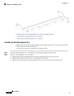
Страница 32: ...om three PSUs In this topic top and bottom refer to the location on the chassis Cable management arms are interchangeable so there is no specific top and bottom cable arm Note For the additional ground requirements see Earth Ground Considerations on page 3 Attach the ground bracket and bottom cable management arms to the chassis a Align the long side of the ground bracket with the threaded standof...

Страница 33: ...dicated in the front and rear layouts do so now See Rail Installation Layout Square Hole Rack on page 26 Also make sure to review Installation Notes and Warnings for the Cisco UCS X9508 Server Chassis on page 1 The chassis must be grounded by a ground lug that Cisco provides or an equivalent See Ground Lug in Earth Ground Considerations on page 3 Before beginning this procedure make sure that the ...

Страница 34: ...u have additional people to help you Tip Step 1 Using a scissor jack chassis lift or other mechanical device lift the chassis and position it so that you can slide it into the rack Step 2 Slide the chassis into the rack until the front flange is flat against the cage nuts Figure 17 Inserting the Chassis into the Rack Step 3 At the front of the chassis remove each of the side trim panels from the c...

Страница 35: ...im Panels Step 4 At the front of the chassis use a 3 Phillips head screwdriver to insert and tighten the eight M6 x 20mm screws through the front mounting flanges Installation 35 Installation Inserting the Chassis into a Square Hole Rack ...

Страница 36: ...ts If you plan to install and ship your chassis in a shippable rack attach the rear mounting brackets See Installing Rear Mounting Brackets Square Hole Rack on page 40 b If you will be installing the chassis in a stationary rack continue the installation procedure See Completing Installation on page 44 Installation 36 Installation Inserting the Chassis into a Square Hole Rack ...

Страница 37: ...the chassis modules compute nodes and components Narrow vertical or horizontal spaces in situations including but not limited to moving the chassis into or out of the shipping container or equipment rack can cause pinch hazards for your hands and fingers Although they do not eliminate the possibility of pinching the chassis has defined grasp points to facilitate handling and moving it For informat...

Страница 38: ...nels are attached magnetically so you should be able to easily pull them off Removing the side trim panels exposes the screw holes in each of the front mounting brackets Keep the side trim panels in a safe location nearby You will replace them when the chassis is installed Note Installation 38 Installation Inserting the Chassis into a Round Hole Rack ...

Страница 39: ...rim Panels Step 4 At the front of the chassis use a 3 Phillips head screwdriver to insert and tighten the eight M6 x 20mm screws through the front mounting flanges Installation 39 Installation Inserting the Chassis into a Round Hole Rack ...

Страница 40: ...rackets See Installing Rear Mounting Brackets Round Hole Rack on page 42 b If you will be installing the chassis in a stationary rack continue the installation procedure See Completing Installation on page 44 Installing Rear Mounting Brackets Square Hole Rack Use this procedure to install the rear mounting tie down brackets UCSX 9508 RACKBK for a chassis that is not pre installed in a rack Install...

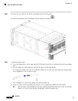
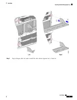
Страница 41: ... into the cutout in the chassis side wall b Slide each rear mounting bracket until the tab seats into the emboss in the chassis top Figure 23 Attaching the Rear Mounting Brackets Step 2 Holding the rear mounting brackets in place use the 3 Phillips head screwdriver to insert the 8 M6 x 20mm screws through the rear mounting brackets then tighten the screws to secure the rear of the chassis to the r...

Страница 42: ...he rack Go to Completing Installation on page 44 Installing Rear Mounting Brackets Round Hole Rack Use this procedure to install the rear mounting tie down brackets UCSX 9508 RACKBK for a chassis that is not pre installed in a rack Installation 42 Installation Installing Rear Mounting Brackets Round Hole Rack ...

Страница 43: ...e into the cutout in the chassis side wall b Slide each rear mounting bracket until the tab seats into the emboss in the chassis top Figure 25 Attaching the Rear Mounting Brackets Step 2 Holding the rear mounting brackets in place use the 3 Phillips head screwdriver to insert the 8 M6 x 20mm screws through the rear mounting brackets then tighten the screws to secure the rear of the chassis to the ...

Страница 44: ...Chassis to the Rack What to do next Complete installing the chassis into the rack Go to Completing Installation on page 44 Completing Installation Continue with installing the chassis Installation 44 Installation Completing Installation ...

Страница 45: ...n runtime Choosing Earth Ground Option The Cisco UCS X9508 server chassis supports connection to facility earth ground through either of the following options side mount which supports connecting the ground cable directly to the chassis through a ground point on one side of the chassis For this option go to Connecting Side Mount Earth Ground on page 45 rear mount which supports connecting the grou...

Страница 46: ...ng lug We recommend 6 AWG wire for the U S installations Make sure to use the proper grounding cable and grounding wire as appropriate for your country or region c Use a crimping tool to secure the grounding cable in the grounding lug d Prepare the other end of the grounding cable and connect it to an appropriate ground point at the facility When the chassis is fully installed the side mount earth...

Страница 47: ...rough the chassis ground bracket which installed at the side of the bottom set of PSUs The facility ground cable must be terminated with the ground lug provided by Cisco or an equivalent For more information see Ground Lug in Earth Ground Considerations on page 3 Use this procedure to connect the chassis to earth ground Before you begin This procedure assumes that you have already attached the bot...

Страница 48: ...g wire as appropriate for your country or region c Use a crimping tool to secure the grounding cable in the grounding lug d Prepare the other end of the grounding cable and connect it to an appropriate ground point at the facility Step 3 Attach the grounding cable to the grounding bracket a Position the ground lug on top of the grounding bracket b Align the terminal holes in the ground lug with th...

Страница 49: ...ement trays for the top and bottom of the chassis You can use one tray for each IFM installed in the Cisco UCS X9508 server chassis but Cisco recommends that you use one tray for all IFM cables The chassis also has cable management arms which organize the PSU cables The cable management arms are different from the cable management tray which organizes IFM cables Because the cable management tray s...

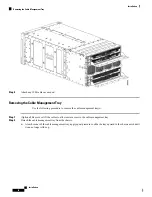
Страница 50: ...the following procedure to install the cable management tray Step 1 Orient the cable management tray so that the hooks are at the top and facing toward the chassis Step 2 Attach the cable management tray to the chassis a Align the hooks on the cable management tray with the rectangular notches in the server chassis b Holding the cable management tray level insert the hooks into the notches c When ...

Страница 51: ...Step 3 Repeat this procedure as needed to install the other cable management trays if needed Installation 51 Installation Installing the Cable Management Tray ...

Страница 52: ...tional Remove or lift the cables to allow easier access to the cable management tray Step 2 Detach the cable management tray from the chassis a At each corner of the cable management tray apply equal pressure to slide the tray upward in the chassis notch until it can no longer slide up Installation 52 Installation Removing the Cable Management Tray ...

Страница 53: ...b Holding the cable management tray level pull it towards you to detach the tray from the chassis Installation 53 Installation Removing the Cable Management Tray ...

Страница 54: ...sp points see Handling the Chassis on page 4 Important Step 6 Gently slide the chassis off the rails and out of the rack Step 7 Replace the modules and compute nodes in the server chassis Repacking the Chassis If you need to repack the chassis remove it from the rack by following the steps in the Removing the Chassis from a Rack on page 54 section When repacking the chassis for return shipment be ...

Отзывы: