


S e n d d o c u m e n t c o m m e n t s t o u c s - d o c f e e d b a c k @ c i s c o . c o m
20
Cisco UCS B250 Extended Memory Blade Server Installation and Service Note
OL-22474-03
Working Inside the Extended Memory Blade Server
Note
The default in the M2 BIOS is low voltage mode, which has the CPU running at 1.35V @ 1066 MHz,
while Performance mode uses 1.5V @ 1333 MHz. You will need to change the BIOS settings to access
Performance mode.
To remove a CPU or heat sink, follow these steps:
Step 1
Unscrew the four captive screws securing the heat sink to the motherboard. See
Figure 10
, callout 1.
N20-X00003 / Xeon E5520
80 W
2.26 GHz
1066
8 MB
N
N20-X00004 / Xeon L5520
60 W
2.26 GHz
1066
8 MB
N
N20-X00006 / Xeon X5550
95 W
2.66 GHz
1333
1
8 MB
N
N20-X00009 / Xeon E5504
80 W
2.00 GHz
800
8 MB
N
1.
While the CPU and DIMMs in an M1 server might in some cases seem to support 1333 DDR, the optimal setting
due to BIOS concerns is 1066.
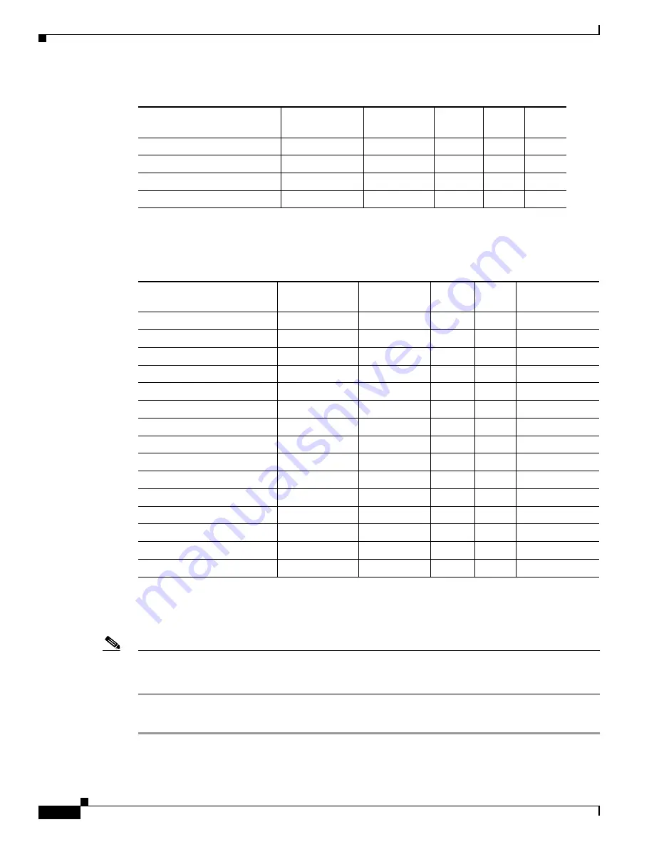
Table 4
CPU Options, M2 Models
Product ID
Power Draw (W) Clock Speed
DDR3
Cache
Low Voltage
Mode
N20-X00001 / Xeon X5570
95 W
2.93 GHz
1333
1
1.
While the CPU and DIMMs in an M1 server might in some cases seem to support 1333 DDR, the optimal setting due to BIOS
concerns is 1066.
8 MB
N
N20-X00002 / Xeon E5540
80 W
2.53 GHz
1066
8 MB
N
N20-X00003 / Xeon E5520
80 W
2.26 GHz
1066
8 MB
N
N20-X00004 / Xeon L5520
60 W
2.26 GHz
1066
8 MB
N
N20-X00006 / Xeon X5550
95 W
2.66 GHz
1333
1
8 MB
N
N20-X00009 / Xeon E5504
80 W
2.00 GHz
800
8 MB
N
A01-X0100 / Xeon X5680
130 W
3.33 GHz
1333
12 MB
Y
A01-X0102 / Xeon X5670
95 W
2.93 GHz
1333
12 MB
Y
A01-X0105 / Xeon X5650
95 W
2.66 GHz
1333
12 MB
Y
A01-X0106 / Xeon L5640
60 W
2.26 GHz
1333
12 MB
Y
A01-X0109 / Xeon E5640
80 W
2.66 GHz
1066
2
2.
If the CPU and DIMM speeds do not match, the system will run at the slower of the two speeds.
12 MB
Y
A01-X0111 / Xeon E5620
80 W
2.40 GHz
1066
2
12 MB
Y
A01-X0115 / Xeon X5690
130 W
3.46 GHz
1333
12 MB
Y
A01-X0117 / Xeon X5675
95W
3.06 GHz
1333
12 MB
Y
A01-X0120 / Xeon E5649
80W
2.53 GHz
1333
12 MB
Y
Table 3
CPU Options, M1 Models (continued)
Product ID
Power Draw (W) Clock Speed
DDR3
Cache
Low
Voltage


