


Installing Cisco TelePresence System Profile 65” Presentation Unit
Page 1
78-19807-02 Profile 65” Presentation Unit Installation Sheet | April 2012 | © 2010-2012 Cisco Systems, Inc. All rights reserved.
3
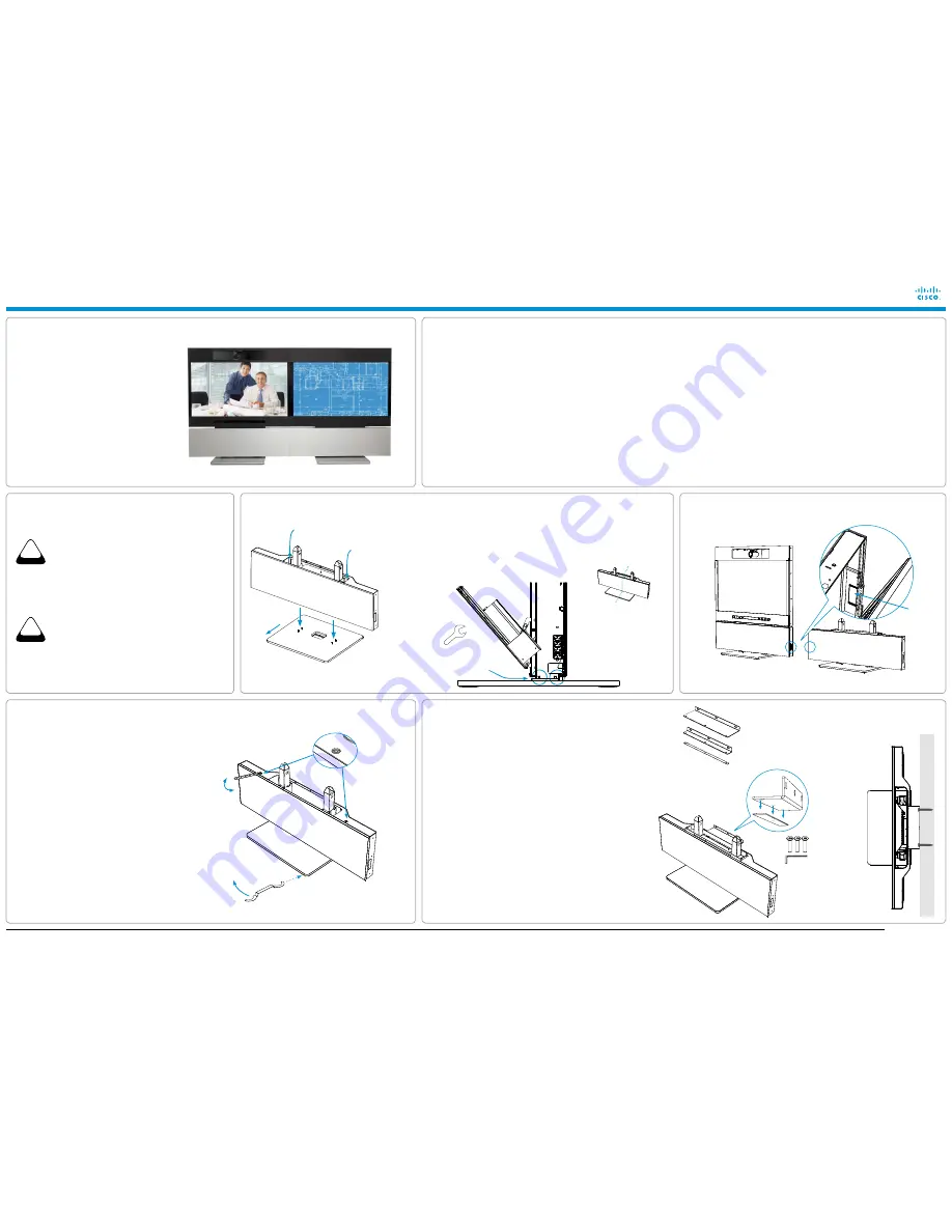
Removing the cable hatch covers
2
Mounting the column to the foot module to complete the bottom module
4
Key lock and level adjustment
The level adjustment tool is found in the foot module box,
and the key lock tool is found in the accessories box.
5
Mounting the wall stand
(applies to wall stand option only)
The wall brackets, bracket spacer, Allen key and screws
are found in the foot module box.
PERSON 1:
Lift here.
PERSON 2:
Lift here.
The illustration shows the stand-alone foot module. The
wall stand foot module is mounted in the same way.
1
Unpacking the unit
FOOT MODULE
(25 kg / 55 LbS)
Open the snap lockers and lift out the foot module box.
Accessories to the foot module:
•
Allen key, orange wrench for levelling adjustment, wall
brackets (wall stand only), spacer (wall stand only),
screws and bolts.
MAIN UNIT
Place the unit on a stable surface, open the snap lockers to
remove outer cover and locate the different parts:
•
Monitor box, grille box, Accessories box, Column, Joint
profile.
Lift out the grille box and accessories box. Remove the
packaging above and around the column and monitor box.
PRECAUTIONS
Follow the steps in this installation guide when unpacking
and assembling the Profile 65” Presentation unit.
This is the second part of the Profile 65” Dual system.
The main part is the Profile 65” system. For further
details see the Profile 65” Installation sheet.
A minimum of four (4) persons are required during the
installation of the system.
•
The monitor box requires four (4) persons to lift.
•
The column requires two (2) persons to lift.
•
The foot module requires two (2) persons to lift.
NOTE:
The floor must be in level.
WEIghTS OF ThE DIFFERENT UNITS
(PACKAgE INCLUDED)
•
Monitor box: 110 kg / 243 lbs
•
Column: 40 kg / 88 lbs
•
Foot module box: 25 kg / 55 lbs
•
Accessories and grille boxes: 7 kg / 15 lbs
UNPACKINg ThE SYSTEM AT ThE DESTINATION
It is highly recommended to unpack and assemble the
Presentation unit at the place where it is to be used.
Check the dimensions of the lift if you need to use a lift
for the transportation.
Outer dimensions and total weight of the main unit
(package included):
•
Height: 145 cm / 57.1 in.
•
Width: 76 cm / 29.9 in.
•
Length: 170 cm / 66.9 in.
•
Weight: 183 kg / 403 lbs
DIMENSIONS (WhEN ASSEMBLED)
The Profile 65” Dual system has the following
dimensions:
•
Height: 167 cm / 65.7 in.
•
Width: 308 cm / 122 in.
•
Depth:
•
Stand-alone: 66 cm / 26 in.
•
Wall stand, with short bracket: 44.7 cm / 17.6 in
•
Wall stand, with long bracket: 52.2 cm / 20.6 in.
•
Joint profile, width: 16 mm / 0.63 in.
USER DOCUMENTATION
User guides and compliance and safety information for
this product are available on the Cisco web site:
http://www.cisco.com/go/profile-docs
ThE PROFILE 65” PRESENTATION UNIT IS DELIvERED WITh:
Monitor
Column
Foot module (stand-alone or wall stand)
grille
Accessories box:
•
Microphone
•
Monitor cable
•
Power cable (optional)
•
Joint profile
•
8
×
Screws M10x30 (Set screw)
•
2
×
Screws M4x40, 2
×
Screw M4x16
•
4
×
Nut plates
•
Tools
NOTE:
The Profile 65” Main system should be
installed before the Presentation unit.
KEY LOCK
Place the orange key on the key lock and turn
clockwise to lock, counter-clockwise to unlock.
Fasten the 4 nuts
(two on each side
of the system).
When mounting the systems together
(see step 6), the cables are lead through the cable hatches.
Main system
Presentation unit
A.
Lift the column and place it carefully on the foot module.
B.
When looking down through the column you can see the four screws in the foot
module. Make sure the screws enter the corresponding holes in the column.
C.
Open the front door to access the screws. Secure the column to the foot module
with four nuts. The nuts are found in the plastic bag. See the illustration below.
Lock
Unlock
Remove the
cable hatch
covers.
Main system
Presentation unit
CAUTION
hEAvY
CAUTION
hEAvY
Both systems:
Open the door and remove
the inner and outer cable hatch covers on
both the main system and the presentation
unit, using a 3 mm Allen key.
LEvELLINg ADJUSTMENT
Place the orange level adjustment tool on the foot
wheel (under the foot plate). Seen from above,
turn clockwise to adjust the height up.
Use the opposite side of the tool and turn
counterclockwise to adjust the height down.
WARNINg
Due to the size and mass of this equipment, it is very
important that the wall stand is safely installed according to
the installation instructions, and that the wall is able to safely
support the product.
It is highly recommended that the wall stand is installed by
trained personnel.
A.
Choose the short or long bracket depending on the required
distance between the bottom module and the wall.
B.
Place the spacer underneath the wall bracket and fasten
the bracket to the bottom module. Re-use the existing three
screws. Use the Allen key, found in the foot module box.
C.
Place the bottom module by the wall, mark where to fasten
the bracket and move away the bottom module.
D.
Add the suitable fixing device for the screws in the wall.
E.
Place the bottom module by the wall and fasten it to the
wall.
The illustration shows
a cross section of
the bottom module
(column and foot
module).
Front
Choose the short or long bracket
depending on the required distance
between the bottom module and
the wall.
Use the spacer between the bottom
module and the wall bracket.
Long wall bracket
Short wall bracket
Spacer