1-34 Cisco 7010 Hardware Installation and Maintenance
Functional Overview
Token Ring Interface Processor (TRIP)
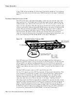
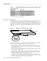
The TRIP, shown in Figure 1-23, provides two or four Token Ring ports for interconnection with
IEEE 802.5 and IBM Token Ring media. The TRIP uses the IBM 16/4-Mbps chipset with an
imbedded performance-enhanced interface driver and a 16.7-MHz bit-slice processor for high-speed
processing. The speed on each port is independently software-configurable for either 4 or 16 Mbps.
The default TRIP microcode resides on a ROM in socket U41.
Figure 1-23
Token Ring Interface Processor (TRIP)
All TRIPs, regardless of whether they provide two or four ports, contain the bank of LEDs shown in
Figure 1-23. As with the other interface processors, the enabled LED is on when the TRIP is enabled
for operation. The three LEDs for each port indicate the following:
•
In Ring—On when the interface is currently active and inserted into the ring. Off when the
interface is not active and is not inserted into a ring.
•
4 Mbps—On when the interface is operating at 4 Mbps.
•
16 Mbps—On when the interface is operating at 16 Mbps.
For complete descriptions of the LED states, refer to the appendix “Reading LED Indicators.”
The TRIP is available with two or four ports. The Cisco 7010 supports up to 3 TRIPs for a maximum
of 12 Token Ring ports. Each port requires a media access unit (MAU) to connect the DB-9 TRIP
connectors to the external Token Ring networks.
For descriptions of Token Ring connectors and MAUs, refer to the section “Token Ring Connection
Equipment” in the chapter “Preparing for Installation.” For descriptions of Token Ring network
connections, refer to the section “Token Ring Connections” in the chapter “Installing the Router.”
Functional Overview
This section describes functions that support the router’s high availability and maintainability.
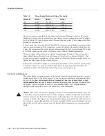
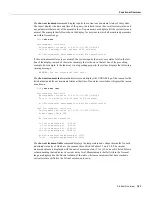
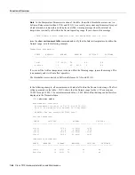
Online insertion and removal (OIR) enables you to quickly install new interfaces without
interrupting system power or shutting down existing interfaces. The environmental monitoring and
reporting functions continuously monitor temperature and voltage points in the system, and provide
reports and warning messages that enable you to quickly locate and resolve problems and maintain
uninterrupted operation. These descriptions will help you become familiar with the capabilities of
the router and the functional differences between the Cisco 7010 and other products.
H2006
U41,
microcode ROM
Enabled
0
1
2
3
16Mbps
4Mbps
IN RING
Содержание TelePresence Server 7010
Страница 10: ...x Cisco 7010 Hardware Installation and Maintenence ...
Страница 14: ...iv Cisco 7010 Hardware Installation and Maintenance Document Conventions ...
Страница 112: ...2 52 Cisco 7010 Hardware Installation and Maintenance Initial Configuration Information Page ________ ...
Страница 148: ...3 36 Cisco 7010 Hardware Installation and Maintenance Using the Flash Memory Card ...
Страница 158: ...4 10 Cisco 7010 Hardware Installation and Maintenance Troubleshooting the Processor Subsystem ...
Страница 242: ...5 84 Cisco 7010 Hardware Installation and Maintenance Replacing Internal Components ...
Страница 258: ...A 16 Cisco 7010 Hardware Installation and Maintenance MIP Interface Cable Pinouts ...
Страница 270: ...B 12 Cisco 7010 Hardware Installation and Maintenance Interface Processor LEDs ...
Страница 274: ...C 4 Cisco 7000 Hardware Installation and Maintenance ...
Страница 287: ...Index 13 ...

